How to Use 10.1'' Screen: Examples, Pinouts, and Specs
Introduction
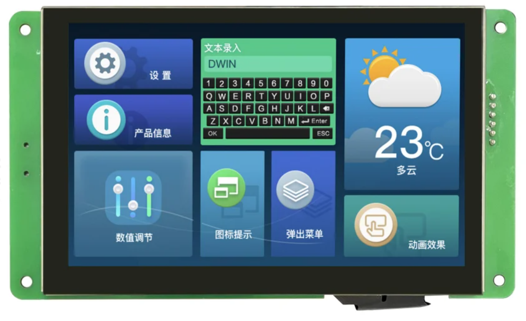
The DWIN DMG10600C101_03W is a high-quality display unit with a 10.1-inch diagonal size. It is commonly used in tablets, laptops, and other electronic devices for visual output. This display unit offers excellent resolution and color accuracy, making it ideal for applications that require clear and vibrant visual representation.
Explore Projects Built with 10.1'' Screen

Explore Projects Built with 10.1'' Screen
Common Applications and Use Cases
- Tablets and Laptops: Used as the primary display for user interfaces.
- Industrial Control Panels: Provides visual feedback and control options.
- Kiosks and Point-of-Sale Systems: Displays information and interactive menus.
- Home Automation Systems: Shows status and control options for smart home devices.
- Medical Devices: Displays critical information and user interfaces.
Technical Specifications
Key Technical Details
| Specification | Value |
|---|---|
| Display Size | 10.1 inches |
| Resolution | 1280 x 800 pixels |
| Aspect Ratio | 16:10 |
| Brightness | 300 cd/m² |
| Contrast Ratio | 800:1 |
| Viewing Angle | 85°/85°/85°/85° (L/R/U/D) |
| Interface | LVDS |
| Operating Voltage | 3.3V |
| Power Consumption | 6W |
| Touch Panel | Optional (Capacitive) |
| Operating Temperature | -20°C to 70°C |
| Storage Temperature | -30°C to 80°C |
Pin Configuration and Descriptions
| Pin Number | Pin Name | Description |
|---|---|---|
| 1 | VCC | Power Supply (3.3V) |
| 2 | GND | Ground |
| 3 | RX | Receive Data (LVDS) |
| 4 | TX | Transmit Data (LVDS) |
| 5 | BL_EN | Backlight Enable |
| 6 | BL_PWM | Backlight PWM Control |
| 7 | TP_INT | Touch Panel Interrupt (Optional) |
| 8 | TP_SCL | Touch Panel I2C Clock (Optional) |
| 9 | TP_SDA | Touch Panel I2C Data (Optional) |
| 10 | NC | Not Connected |
Usage Instructions
How to Use the Component in a Circuit
Power Supply:
- Connect the VCC pin to a 3.3V power supply.
- Connect the GND pin to the ground of your circuit.
Data Interface:
- Connect the RX and TX pins to the LVDS interface of your controller.
Backlight Control:
- Connect the BL_EN pin to a GPIO pin on your controller to enable/disable the backlight.
- Use the BL_PWM pin to control the brightness of the backlight using PWM signals.
Touch Panel (Optional):
- If using the touch panel, connect the TP_INT, TP_SCL, and TP_SDA pins to the corresponding pins on your controller.
Important Considerations and Best Practices
- Power Supply: Ensure that the power supply is stable and within the specified voltage range to avoid damaging the display.
- Signal Integrity: Use proper shielding and grounding techniques to minimize noise and interference in the LVDS signals.
- Backlight Control: Use appropriate PWM frequencies to avoid flickering and ensure smooth brightness control.
- Touch Panel: If using the touch panel, ensure that the I2C bus is properly terminated and that pull-up resistors are used as needed.
Troubleshooting and FAQs
Common Issues Users Might Face
No Display Output:
- Solution: Check the power supply connections and ensure that the VCC and GND pins are properly connected. Verify that the LVDS signals are correctly connected and that the controller is properly configured.
Flickering Backlight:
- Solution: Adjust the PWM frequency for the backlight control. Ensure that the BL_EN and BL_PWM pins are properly connected and that the PWM signal is stable.
Touch Panel Not Responding:
- Solution: Verify the connections for the touch panel interface (TP_INT, TP_SCL, TP_SDA). Ensure that the I2C bus is properly terminated and that the touch panel is enabled in the controller's firmware.
Solutions and Tips for Troubleshooting
- Check Connections: Ensure that all connections are secure and that there are no loose wires or poor solder joints.
- Verify Power Supply: Use a multimeter to check the voltage levels at the VCC and GND pins to ensure that the power supply is within the specified range.
- Inspect Signal Integrity: Use an oscilloscope to check the LVDS signals for any noise or interference that could affect the display performance.
- Update Firmware: Ensure that the controller's firmware is up to date and properly configured for the display unit.
Example Code for Arduino UNO
#include <Wire.h>

// Define pin connections
#define BL_EN_PIN 9
#define BL_PWM_PIN 10

void setup() {
  // Initialize serial communication
  Serial.begin(9600);

  // Set pin modes
  pinMode(BL_EN_PIN, OUTPUT);
  pinMode(BL_PWM_PIN, OUTPUT);

  // Enable backlight
  digitalWrite(BL_EN_PIN, HIGH);

  // Set initial brightness (50%)
  analogWrite(BL_PWM_PIN, 128);
}

void loop() {
  // Example: Adjust brightness using serial input
  if (Serial.available() > 0) {
    int brightness = Serial.parseInt();
    if (brightness >= 0 && brightness <= 255) {
      analogWrite(BL_PWM_PIN, brightness);
    }
  }
}
This example code demonstrates how to control the backlight of the DWIN DMG10600C101_03W display using an Arduino UNO. The backlight enable pin (BL_EN) is connected to pin 9, and the backlight PWM control pin (BL_PWM) is connected to pin 10. The brightness can be adjusted using serial input.
By following this documentation, users can effectively integrate and utilize the DWIN DMG10600C101_03W 10.1'' screen in their projects, ensuring optimal performance and reliability.