
How to Use Ozone 2 Click: Examples, Pinouts, and Specs
 Design with Ozone 2 Click in Cirkit Designer
Introduction
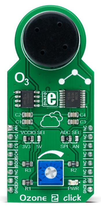
The Ozone 2 Click by MIKROE is a compact and reliable sensor module designed for measuring ozone (O₃) concentration in the air. It features the MQ131 high-precision ozone sensor, which provides accurate and stable readings. The module communicates via the I2C interface, making it easy to integrate into various microcontroller-based systems. This sensor is ideal for applications such as environmental monitoring, air quality assessment, and industrial safety systems.
Explore Projects Built with Ozone 2 Click
 Open Project in Cirkit Designer
 Open Project in Cirkit Designer
 Open Project in Cirkit Designer
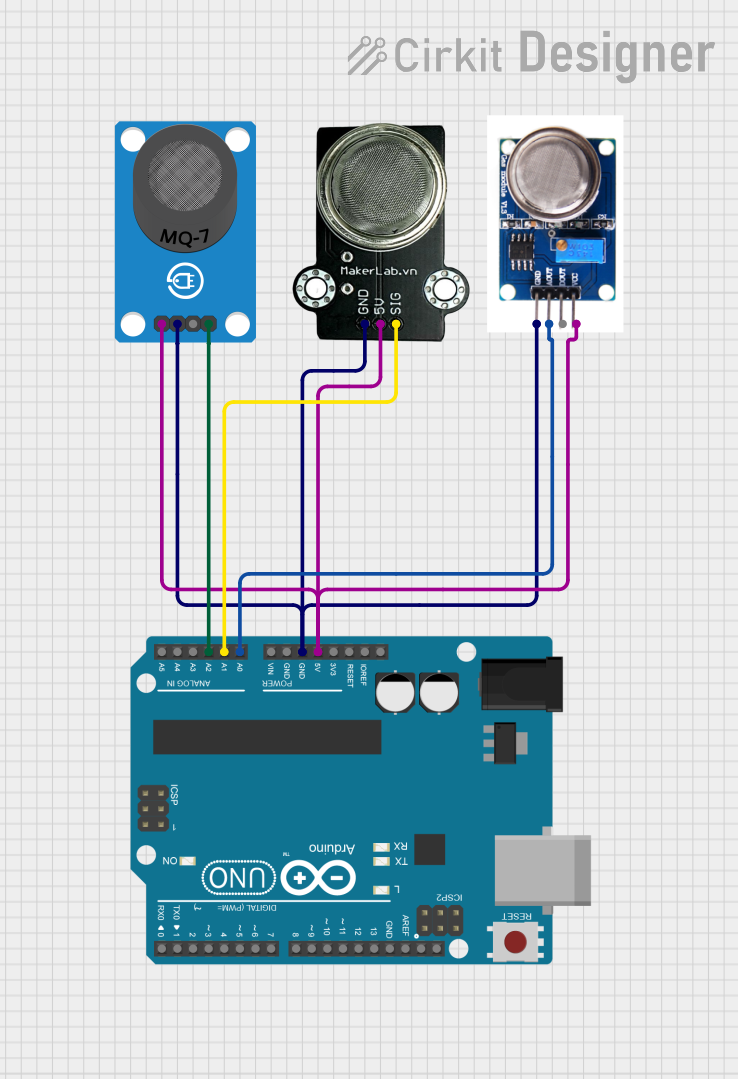 Open Project in Cirkit Designer
Explore Projects Built with Ozone 2 Click
Open Project in Cirkit DesignerOpen Project in Cirkit DesignerOpen Project in Cirkit DesignerOpen Project in Cirkit DesignerCommon Applications
- Environmental monitoring systems
- Air quality control in residential and industrial areas
- Smart home automation for air purification
- Industrial safety systems to detect harmful ozone levels
- Research and development in atmospheric studies
Technical Specifications
Key Technical Details
| Parameter | Value |
|---|---|
| Sensor Model | MQ131 |
| Measurement Range | 10 ppb to 2 ppm (parts per million) |
| Communication Interface | I2C |
| Operating Voltage | 3.3V or 5V (selectable via jumper) |
| Operating Temperature | -10°C to +50°C |
| Operating Humidity | 15% to 90% RH (non-condensing) |
| Dimensions | 25.4mm x 57.15mm |
Pin Configuration and Descriptions
The Ozone 2 Click module uses a standard mikroBUS™ socket. Below is the pinout description:
| Pin Name | mikroBUS™ Pin | Description |
|---|---|---|
| AN | AN | Analog output (not used in I2C mode) |
| RST | RST | Reset pin (optional) |
| CS | CS | Chip select (not used in I2C mode) |
| SCK | SCL | I2C clock line |
| MISO | SDA | I2C data line |
| MOSI | NC | Not connected |
| PWM | NC | Not connected |
| INT | NC | Not connected |
| 3.3V | 3.3V | Power supply (3.3V) |
| 5V | 5V | Power supply (5V) |
| GND | GND | Ground |
Usage Instructions
How to Use the Ozone 2 Click in a Circuit
- Power Supply: Connect the module to a 3.3V or 5V power source, depending on your system's requirements. Ensure the onboard jumper is set to the correct voltage.
- I2C Communication: Connect the SCL (clock) and SDA (data) pins to the corresponding I2C pins on your microcontroller.
- Initialization: Configure the I2C interface on your microcontroller to communicate with the Ozone 2 Click. The default I2C address is typically provided in the module's datasheet.
- Reading Data: Use the I2C protocol to read ozone concentration data from the sensor. The data is typically provided in parts per million (ppm).
Important Considerations and Best Practices
- Preheating: The MQ131 sensor requires a preheating period (typically 24 hours) for optimal accuracy during the first use.
- Calibration: For precise measurements, calibrate the sensor in a controlled environment with known ozone concentrations.
- Ventilation: Ensure proper airflow around the sensor for accurate readings.
- Avoid Contaminants: Keep the sensor away from dust, oil, and other contaminants that may affect its performance.
- Temperature and Humidity: Operate the sensor within the specified temperature and humidity range for reliable results.
Example Code for Arduino UNO
Below is an example of how to interface the Ozone 2 Click with an Arduino UNO using the I2C protocol:
#include <Wire.h>

// Define the I2C address of the Ozone 2 Click module
#define OZONE2_I2C_ADDRESS 0x48

void setup() {
  Wire.begin(); // Initialize I2C communication
  Serial.begin(9600); // Initialize serial communication for debugging

  Serial.println("Ozone 2 Click Initialization...");
}

void loop() {
  Wire.beginTransmission(OZONE2_I2C_ADDRESS); // Start communication with the sensor
  Wire.write(0x00); // Request data from the sensor (register 0x00)
  Wire.endTransmission();

  Wire.requestFrom(OZONE2_I2C_ADDRESS, 2); // Request 2 bytes of data
  if (Wire.available() == 2) {
    uint8_t msb = Wire.read(); // Read the most significant byte
    uint8_t lsb = Wire.read(); // Read the least significant byte

    // Combine the two bytes into a single 16-bit value
    uint16_t ozoneData = (msb << 8) | lsb;

    // Convert the raw data to ppm (example conversion, adjust as needed)
    float ozonePPM = ozoneData * 0.1;

    // Print the ozone concentration to the serial monitor
    Serial.print("Ozone Concentration: ");
    Serial.print(ozonePPM);
    Serial.println(" ppm");
  } else {
    Serial.println("Failed to read data from Ozone 2 Click.");
  }

  delay(1000); // Wait for 1 second before the next reading
}
Troubleshooting and FAQs
Common Issues and Solutions
No Data Received from the Sensor
- Cause: Incorrect I2C wiring or address mismatch.
- Solution: Verify the I2C connections (SCL and SDA) and ensure the correct I2C address is used in the code.
Inaccurate Readings
- Cause: Sensor not preheated or improperly calibrated.
- Solution: Allow the sensor to preheat for the recommended duration and calibrate it in a controlled environment.
Sensor Not Responding
- Cause: Incorrect power supply voltage.
- Solution: Check the onboard jumper setting and ensure the correct voltage (3.3V or 5V) is supplied.
Fluctuating Readings
- Cause: Poor ventilation or environmental interference.
- Solution: Ensure proper airflow around the sensor and avoid placing it near sources of interference.
FAQs
Q1: Can the Ozone 2 Click measure other gases?
A1: No, the Ozone 2 Click is specifically designed to measure ozone (O₃) concentration. It is not suitable for detecting other gases.
Q2: How long does the sensor last?
A2: The MQ131 sensor has a typical lifespan of 2-3 years under normal operating conditions. Proper maintenance and usage can extend its lifespan.
Q3: Can I use the Ozone 2 Click with a 5V microcontroller?
A3: Yes, the module supports both 3.3V and 5V operation. Ensure the onboard jumper is set to the appropriate voltage.
Q4: Is the sensor waterproof?
A4: No, the sensor is not waterproof. Avoid exposing it to water or high humidity levels beyond the specified range.
This concludes the documentation for the Ozone 2 Click module. For further assistance, refer to the official datasheet or contact MIKROE support.