Cirkit Designer Logo
Cirkit Designer
Your all-in-one circuit design IDE
Home / 
Component Documentation

How to Use MT3608: Examples, Pinouts, and Specs

Image of MT3608
Cirkit Designer LogoDesign with MT3608 in Cirkit Designer

Introduction

The MT3608 is a high-efficiency step-up (boost) DC-DC converter designed to increase an input voltage to a higher output voltage. It is widely used in applications where a stable, higher voltage is required from a lower voltage source, such as in battery-powered devices. The MT3608 is compact, cost-effective, and highly efficient, making it a popular choice for hobbyists and professionals alike.

Explore Projects Built with MT3608

Use Cirkit Designer to design, explore, and prototype these projects online. Some projects support real-time simulation. Click "Open Project" to start designing instantly!
ESP32-Controlled Bluetooth Robotic Vehicle with MT3608 Boost Converters and L298N Motor Drivers
Image of Copy of Diagrama Elétrico - AutoBots (1): A project utilizing MT3608 in a practical application
This circuit is designed to control multiple DC motors and a servo motor using an ESP32 microcontroller, which is interfaced with Bluetooth for wireless control commands. The ESP32 outputs control signals to two L298N motor drivers, which in turn drive the DC motors. The MT3608 modules are used to step up the voltage from a 4 x AAA battery mount to power the motor drivers, while the servo motor is directly controlled by the ESP32.
Cirkit Designer LogoOpen Project in Cirkit Designer
Voltage Regulation System with MT3608 Boost and LM2596 Buck Converters
Image of solar system router ups: A project utilizing MT3608 in a practical application
This circuit consists of two MT3608 boost converters and an LM2596 step-down module, each connected to separate 12V power supplies. The MT3608 modules are configured to step up the voltage from their respective power supplies, while the LM2596 module steps down the voltage from a 12V battery. Diodes are used to ensure correct current flow direction, potentially for protection or isolation between different parts of the circuit.
Cirkit Designer LogoOpen Project in Cirkit Designer
ESP32-Powered Obstacle Avoidance Robot with IR and Ultrasonic Sensors
Image of projcememek: A project utilizing MT3608 in a practical application
This circuit features a 18650 Li-Ion battery connected to a TP4056 charging module, which in turn is connected to an MT3608 boost converter to step up the voltage. The output of the MT3608 powers an ESP32 microcontroller, a TCRT 5000 IR sensor, an HC-SR04 ultrasonic sensor, and an MG996R servo motor. The ESP32 is configured to control the servo motor via GPIO 27 and to receive input signals from the IR sensor and ultrasonic sensor through GPIO 14 and GPIO 13, respectively.
Cirkit Designer LogoOpen Project in Cirkit Designer
ESP32-Controlled Traffic Light and DC Motors with MT3608 Boost Converters
Image of Diagrama Elétrico - AutoBots: A project utilizing MT3608 in a practical application
This circuit is designed to control a traffic light and multiple DC motors using an ESP32 microcontroller. The ESP32's GPIO pins are connected to the traffic light to control the green, yellow, and red LEDs, and to the L298N motor drivers for controlling the speed and direction of the DC motors. The MT3608 modules are used to step up the voltage from the AAA batteries to power the motor drivers, and the MG996R servo is controlled by the ESP32 for additional actuation tasks.
Cirkit Designer LogoOpen Project in Cirkit Designer

Explore Projects Built with MT3608

Use Cirkit Designer to design, explore, and prototype these projects online. Some projects support real-time simulation. Click "Open Project" to start designing instantly!
Image of Copy of Diagrama Elétrico - AutoBots (1): A project utilizing MT3608 in a practical application
ESP32-Controlled Bluetooth Robotic Vehicle with MT3608 Boost Converters and L298N Motor Drivers
This circuit is designed to control multiple DC motors and a servo motor using an ESP32 microcontroller, which is interfaced with Bluetooth for wireless control commands. The ESP32 outputs control signals to two L298N motor drivers, which in turn drive the DC motors. The MT3608 modules are used to step up the voltage from a 4 x AAA battery mount to power the motor drivers, while the servo motor is directly controlled by the ESP32.
Cirkit Designer LogoOpen Project in Cirkit Designer
Image of solar system router ups: A project utilizing MT3608 in a practical application
Voltage Regulation System with MT3608 Boost and LM2596 Buck Converters
This circuit consists of two MT3608 boost converters and an LM2596 step-down module, each connected to separate 12V power supplies. The MT3608 modules are configured to step up the voltage from their respective power supplies, while the LM2596 module steps down the voltage from a 12V battery. Diodes are used to ensure correct current flow direction, potentially for protection or isolation between different parts of the circuit.
Cirkit Designer LogoOpen Project in Cirkit Designer
Image of projcememek: A project utilizing MT3608 in a practical application
ESP32-Powered Obstacle Avoidance Robot with IR and Ultrasonic Sensors
This circuit features a 18650 Li-Ion battery connected to a TP4056 charging module, which in turn is connected to an MT3608 boost converter to step up the voltage. The output of the MT3608 powers an ESP32 microcontroller, a TCRT 5000 IR sensor, an HC-SR04 ultrasonic sensor, and an MG996R servo motor. The ESP32 is configured to control the servo motor via GPIO 27 and to receive input signals from the IR sensor and ultrasonic sensor through GPIO 14 and GPIO 13, respectively.
Cirkit Designer LogoOpen Project in Cirkit Designer
Image of Diagrama Elétrico - AutoBots: A project utilizing MT3608 in a practical application
ESP32-Controlled Traffic Light and DC Motors with MT3608 Boost Converters
This circuit is designed to control a traffic light and multiple DC motors using an ESP32 microcontroller. The ESP32's GPIO pins are connected to the traffic light to control the green, yellow, and red LEDs, and to the L298N motor drivers for controlling the speed and direction of the DC motors. The MT3608 modules are used to step up the voltage from the AAA batteries to power the motor drivers, and the MG996R servo is controlled by the ESP32 for additional actuation tasks.
Cirkit Designer LogoOpen Project in Cirkit Designer

Common Applications

  • Powering LEDs, sensors, and microcontrollers from low-voltage batteries
  • Portable electronics and battery-powered devices
  • Solar-powered systems
  • DIY electronics projects requiring voltage conversion

Technical Specifications

The MT3608 is available as a module or as an IC. Below are the key technical details:

Key Specifications

Parameter Value
Input Voltage Range 2V to 24V
Output Voltage Range Up to 28V (adjustable)
Maximum Output Current 2A (dependent on input voltage)
Efficiency Up to 93%
Switching Frequency 1.2 MHz
Operating Temperature -40°C to +85°C

Pin Configuration (MT3608 IC)

Pin Number Pin Name Description
1 SW Switching node (connects to inductor)
2 GND Ground
3 FB Feedback pin (used to set output voltage)
4 EN Enable pin (active high, enables the converter)
5 VIN Input voltage supply
6 VOUT Output voltage (connects to load)

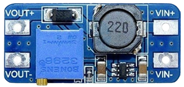
Pin Configuration (MT3608 Module)

Pin Name Description
VIN Input voltage (connect to power source)
GND Ground
VOUT Output voltage (connect to load)
ADJ Adjustable potentiometer (sets output voltage)

Usage Instructions

How to Use the MT3608 in a Circuit

  1. Connect the Input Voltage:

    • Connect the positive terminal of your power source to the VIN pin.
    • Connect the negative terminal of your power source to the GND pin.
    • Ensure the input voltage is within the range of 2V to 24V.
  2. Set the Output Voltage:

    • Use the onboard potentiometer (on the module) to adjust the output voltage.
    • Turn the potentiometer clockwise to increase the output voltage and counterclockwise to decrease it.
    • Use a multimeter to measure the output voltage at the VOUT pin while adjusting.
  3. Connect the Load:

    • Connect the positive terminal of your load to the VOUT pin.
    • Connect the negative terminal of your load to the GND pin.
  4. Enable the Converter:

    • If using the MT3608 IC, ensure the EN pin is pulled high to enable the converter.

Important Considerations

  • Input Voltage: Ensure the input voltage is within the specified range (2V to 24V). Exceeding this range may damage the module or IC.
  • Output Voltage: Do not exceed the maximum output voltage of 28V.
  • Current Limit: The maximum output current is 2A, but this depends on the input voltage and the efficiency of the circuit. Exceeding this limit may cause overheating or damage.
  • Heat Dissipation: For high-power applications, consider adding a heatsink to the module to improve heat dissipation.
  • Inductor Selection: If using the MT3608 IC in a custom circuit, choose an appropriate inductor value (typically 4.7µH to 22µH) based on your application.

Example: Using MT3608 with Arduino UNO

The MT3608 can be used to power an Arduino UNO from a low-voltage battery. Below is an example:

  1. Connect a 3.7V Li-ion battery to the VIN and GND pins of the MT3608 module.
  2. Adjust the potentiometer to set the output voltage to 5V.
  3. Connect the VOUT and GND pins of the MT3608 to the 5V and GND pins of the Arduino UNO.

Here is a simple Arduino code to blink an LED:

// Blink an LED connected to pin 13 of the Arduino UNO
void setup() {
  pinMode(13, OUTPUT); // Set pin 13 as an output
}

void loop() {
  digitalWrite(13, HIGH); // Turn the LED on
  delay(1000);            // Wait for 1 second
  digitalWrite(13, LOW);  // Turn the LED off
  delay(1000);            // Wait for 1 second
}

Troubleshooting and FAQs

Common Issues

  1. No Output Voltage:

    • Check the input voltage and ensure it is within the specified range.
    • Verify that the EN pin is pulled high (if using the IC).
    • Ensure all connections are secure and correct.
  2. Output Voltage is Unstable:

    • Check the load current and ensure it does not exceed the maximum limit.
    • Verify the inductor value and ensure it is appropriate for your application.
    • Add a capacitor (e.g., 10µF) across the output to stabilize the voltage.
  3. Overheating:

    • Ensure the input and output currents are within the specified limits.
    • Add a heatsink or improve ventilation around the module.

FAQs

Q: Can the MT3608 step down voltage?
A: No, the MT3608 is a step-up (boost) converter and cannot step down voltage. For step-down applications, use a buck converter.

Q: How do I calculate the output voltage?
A: For the MT3608 IC, the output voltage is set using a resistor divider connected to the FB pin. For the module, adjust the potentiometer while monitoring the output voltage with a multimeter.

Q: Can I use the MT3608 with a solar panel?
A: Yes, the MT3608 can be used with a solar panel as long as the input voltage is within the specified range. Ensure the solar panel provides sufficient current for your load.

Q: What is the efficiency of the MT3608?
A: The MT3608 has an efficiency of up to 93%, depending on the input voltage, output voltage, and load conditions.