How to Use Load Cell Amp: Examples, Pinouts, and Specs
Introduction
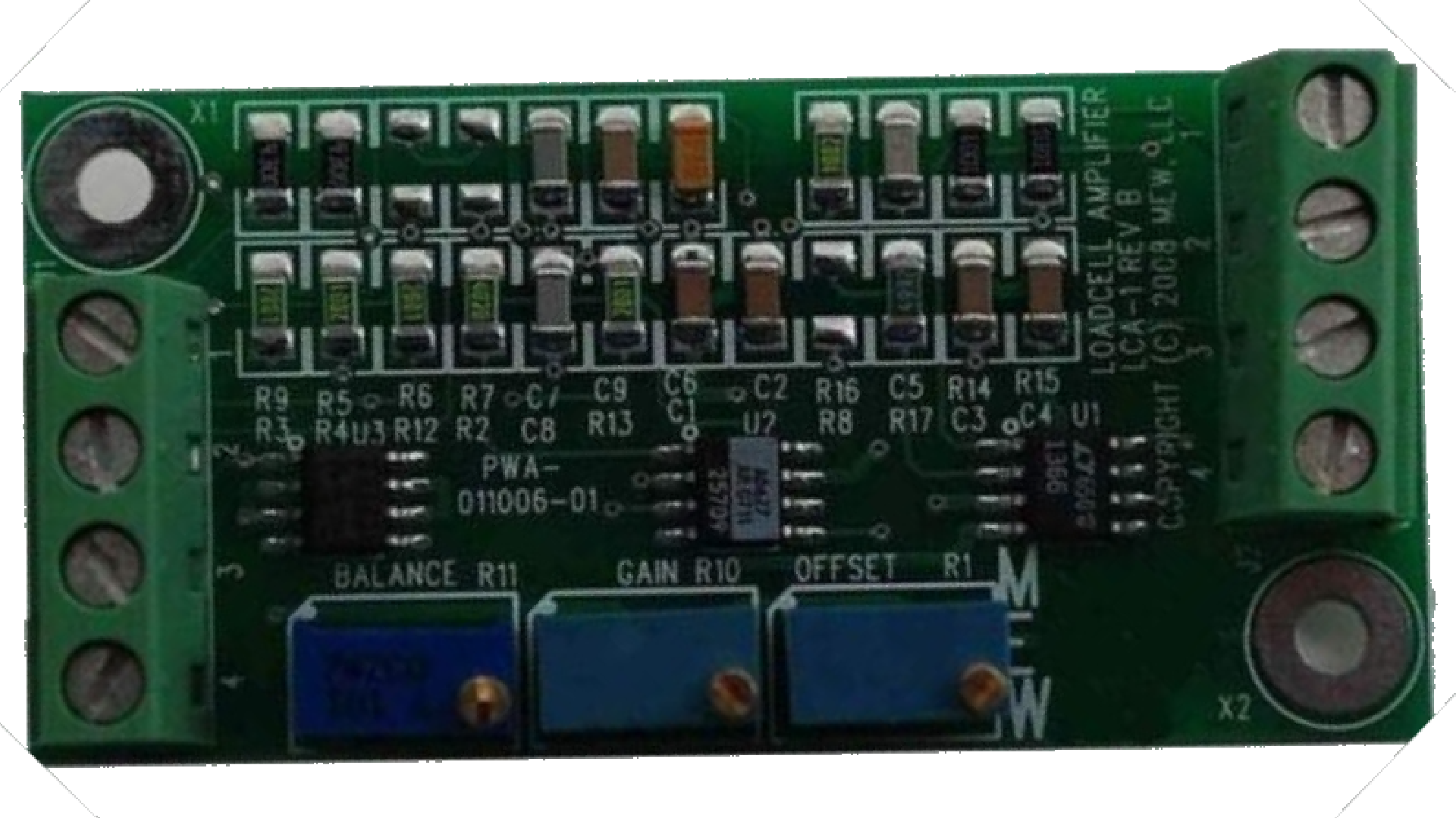
The Load Cell Amplifier (LCA1), manufactured by Moonlite Electro Werks, is a precision electronic device designed to amplify the small electrical signals generated by load cells. Load cells are commonly used in weight measurement and force sensing applications, and the LCA1 ensures that these signals are converted into a more usable form for further processing or display.
Explore Projects Built with Load Cell Amp


Explore Projects Built with Load Cell Amp
Common Applications and Use Cases
- Digital weighing scales
- Industrial force measurement systems
- Robotics and automation for weight sensing
- Laboratory equipment for material testing
- IoT-based weight monitoring systems
The LCA1 is ideal for applications requiring accurate and reliable signal amplification from strain gauge-based load cells.
Technical Specifications
Key Technical Details
| Parameter | Specification |
|---|---|
| Manufacturer | Moonlite Electro Werks |
| Part ID | LCA1 |
| Input Voltage Range | 3.3V to 5V DC |
| Output Voltage Range | 0V to 3.3V (analog output) |
| Amplification Factor | Adjustable (via onboard potentiometer) |
| Input Signal Range | ±20mV (typical for load cells) |
| Operating Temperature | -10°C to 50°C |
| Dimensions | 25mm x 20mm x 5mm |
Pin Configuration and Descriptions
| Pin Name | Pin Number | Description |
|---|---|---|
| VCC | 1 | Power supply input (3.3V to 5V DC) |
| GND | 2 | Ground connection |
| IN+ | 3 | Positive input from load cell |
| IN- | 4 | Negative input from load cell |
| OUT | 5 | Amplified analog output signal |
Usage Instructions
How to Use the LCA1 in a Circuit
- Power the Amplifier: Connect the VCC pin to a 3.3V or 5V DC power source and the GND pin to the ground of your circuit.
- Connect the Load Cell: Attach the positive and negative signal wires of the load cell to the IN+ and IN- pins of the LCA1, respectively.
- Adjust the Gain: Use the onboard potentiometer to adjust the amplification factor. This allows you to fine-tune the output signal based on the load cell's sensitivity and your application's requirements.
- Read the Output: The amplified signal will be available at the OUT pin. This can be connected to an ADC (Analog-to-Digital Converter) or a microcontroller for further processing.
Important Considerations and Best Practices
- Ensure that the load cell is properly calibrated before use to achieve accurate measurements.
- Use shielded cables for the load cell connections to minimize noise interference.
- Avoid exposing the LCA1 to extreme temperatures or moisture, as this may affect its performance.
- When connecting to a microcontroller, ensure that the ADC input voltage range matches the LCA1's output range (0V to 3.3V).
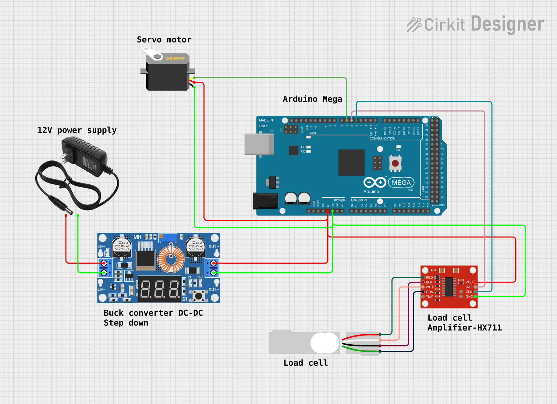
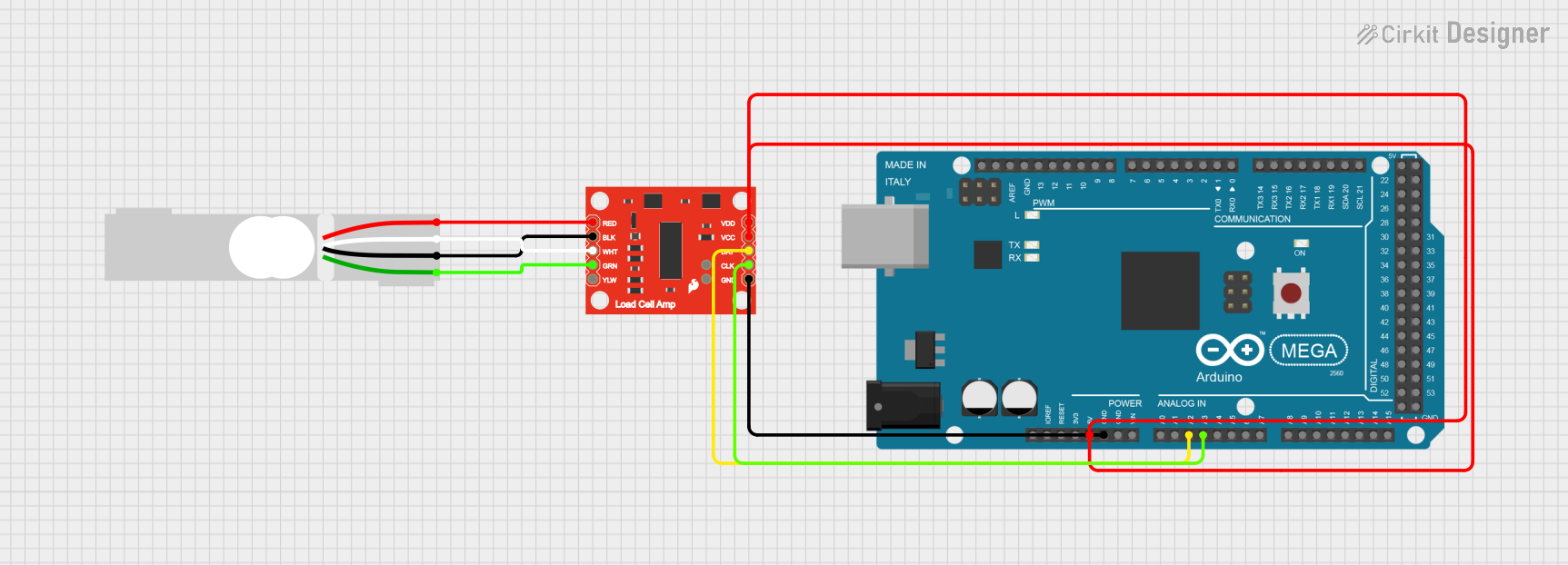
Example: Connecting the LCA1 to an Arduino UNO
Below is an example of how to connect the LCA1 to an Arduino UNO and read the amplified signal:
Circuit Connections
- LCA1 VCC → Arduino 5V
- LCA1 GND → Arduino GND
- LCA1 OUT → Arduino A0 (Analog Pin)
- Load Cell IN+ and IN- → Connect to the LCA1 IN+ and IN- pins
Arduino Code
// Load Cell Amplifier (LCA1) Example Code
// This code reads the amplified signal from the LCA1 and displays it in the Serial Monitor.

const int loadCellPin = A0; // Analog pin connected to LCA1 OUT pin

void setup() {
  Serial.begin(9600); // Initialize serial communication at 9600 baud
  pinMode(loadCellPin, INPUT); // Set the load cell pin as input
}

void loop() {
  int sensorValue = analogRead(loadCellPin); // Read the analog value from LCA1
  float voltage = (sensorValue / 1023.0) * 5.0; // Convert to voltage (assuming 5V ADC reference)

  // Display the raw sensor value and voltage
  Serial.print("Raw Value: ");
  Serial.print(sensorValue);
  Serial.print(" | Voltage: ");
  Serial.print(voltage, 3); // Display voltage with 3 decimal places
  Serial.println(" V");

  delay(500); // Wait for 500ms before the next reading
}
Troubleshooting and FAQs
Common Issues and Solutions
No Output Signal
- Cause: Incorrect wiring or loose connections.
- Solution: Double-check all connections, especially the load cell and power supply.
Fluctuating or Noisy Output
- Cause: Electrical noise or interference.
- Solution: Use shielded cables for the load cell and ensure proper grounding.
Output Signal Saturation
- Cause: Gain set too high.
- Solution: Adjust the potentiometer to reduce the amplification factor.
Inaccurate Measurements
- Cause: Load cell not calibrated or improper load cell selection.
- Solution: Calibrate the load cell and ensure it matches the LCA1's input range.
FAQs
Q: Can the LCA1 be used with a 3.3V microcontroller?
A: Yes, the LCA1 operates within a 3.3V to 5V range, making it compatible with 3.3V microcontrollers like the ESP32 or Raspberry Pi Pico.
Q: How do I calibrate the load cell with the LCA1?
A: Calibration involves applying known weights to the load cell and adjusting the gain (via the potentiometer) or using software to map the output signal to the corresponding weights.
Q: What is the maximum load cell signal the LCA1 can handle?
A: The LCA1 is designed for load cells with a typical signal range of ±20mV. Ensure your load cell operates within this range for optimal performance.
This concludes the documentation for the Load Cell Amp (LCA1). For further assistance, refer to the manufacturer's support resources or contact Moonlite Electro Werks directly.