Cirkit Designer Logo
Cirkit Designer
Your all-in-one circuit design IDE
Home / 
Component Documentation

How to Use 4 Solid State Relay: Examples, Pinouts, and Specs

Image of 4 Solid State Relay
Cirkit Designer LogoDesign with 4 Solid State Relay in Cirkit Designer

Introduction

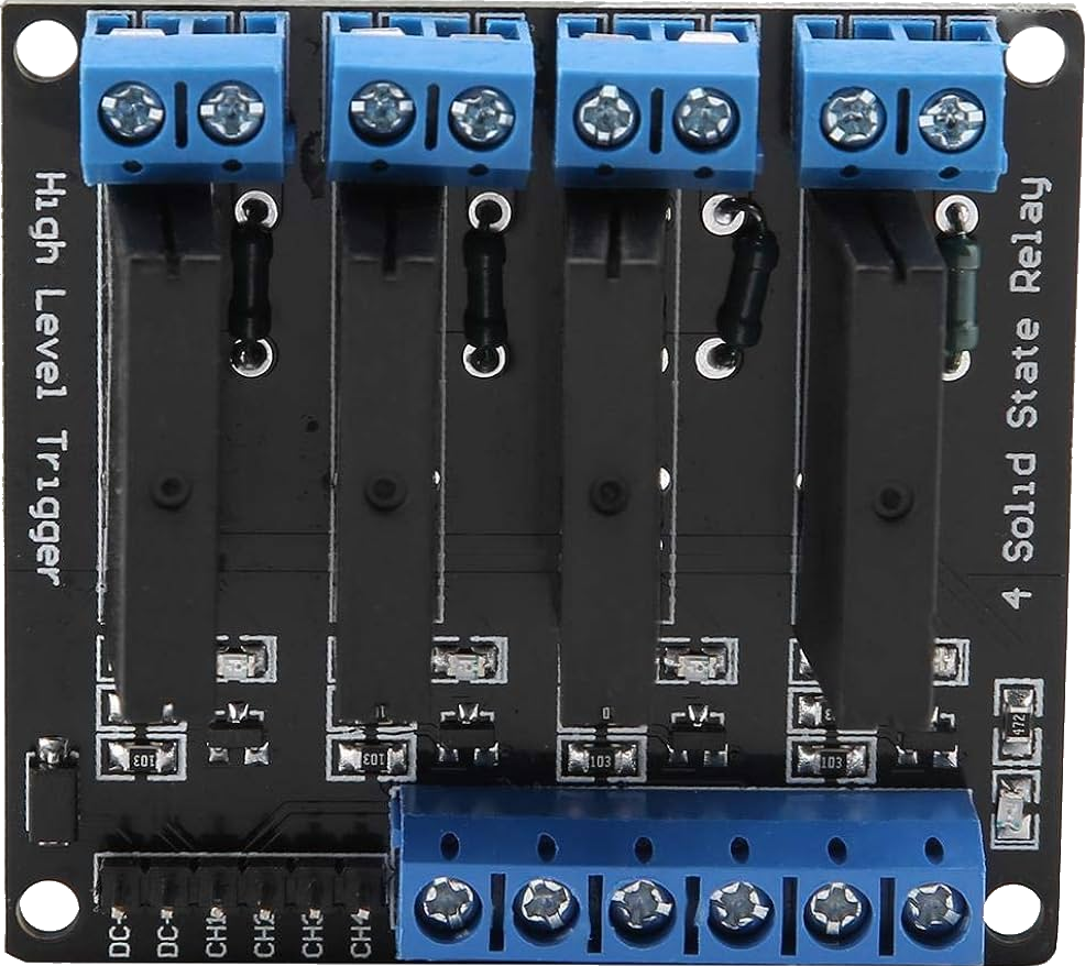
A 4-Channel Solid State Relay (SSR) module is an electronic switching device that allows for the control of high power devices using low voltage signals. Each channel of the SSR module can be controlled independently, making it suitable for applications that require multiple high-power outputs to be controlled simultaneously. Common applications include industrial automation, home automation, and any project requiring the interfacing of a microcontroller, like an Arduino, with high-power electrical loads.

Explore Projects Built with 4 Solid State Relay

Use Cirkit Designer to design, explore, and prototype these projects online. Some projects support real-time simulation. Click "Open Project" to start designing instantly!
Battery-Powered 4-Channel Relay Control with LED Indicators
Image of RELLAY BOARD TEST: A project utilizing 4 Solid State Relay in a practical application
This circuit consists of a 5V battery powering a 4-channel relay module, which controls four LEDs (red, yellow, green, and blue) through individual resistors. Each relay channel is activated by a corresponding SPST toggle switch, allowing manual control of the LEDs.
Cirkit Designer LogoOpen Project in Cirkit Designer
ESP8266 NodeMCU Controlled Smart Home Automation System
Image of home automation: A project utilizing 4 Solid State Relay in a practical application
This is a smart control system utilizing an ESP8266 NodeMCU to manage various devices through a 4-channel relay, with input from an LDR module and a PIR sensor. It is designed for both manual and automatic control, powered by a Li-ion battery and 240V AC source.
Cirkit Designer LogoOpen Project in Cirkit Designer
Wi-Fi Controlled Smart Lighting System with ESP8266 and Relay Module
Image of MCU home automation: A project utilizing 4 Solid State Relay in a practical application
This circuit is designed to control four AC bulbs using an ESP8266 NodeMCU microcontroller and a 4-channel relay module. The ESP8266 receives commands via a Wi-Fi connection to toggle the state of each relay, which in turn switches the connected AC bulbs on or off. Additionally, there are rocker switches that can manually override the relay states, and the system is designed to synchronize the relay states with the manual switches and report the status to a remote server.
Cirkit Designer LogoOpen Project in Cirkit Designer
Wi-Fi Controlled Relay System with ESP32 and LED Indicators
Image of GIZMO_CONTROL_ONLY: A project utilizing 4 Solid State Relay in a practical application
This circuit is a control system using an ESP32 microcontroller to manage a 4-channel relay module, which in turn controls various loads. The relays are activated by rocker switches and provide visual feedback through LEDs, while power is supplied and regulated by an HLK-PM12 module and protected by a fuse and circuit breaker.
Cirkit Designer LogoOpen Project in Cirkit Designer

Explore Projects Built with 4 Solid State Relay

Use Cirkit Designer to design, explore, and prototype these projects online. Some projects support real-time simulation. Click "Open Project" to start designing instantly!
Image of RELLAY BOARD TEST: A project utilizing 4 Solid State Relay in a practical application
Battery-Powered 4-Channel Relay Control with LED Indicators
This circuit consists of a 5V battery powering a 4-channel relay module, which controls four LEDs (red, yellow, green, and blue) through individual resistors. Each relay channel is activated by a corresponding SPST toggle switch, allowing manual control of the LEDs.
Cirkit Designer LogoOpen Project in Cirkit Designer
Image of home automation: A project utilizing 4 Solid State Relay in a practical application
ESP8266 NodeMCU Controlled Smart Home Automation System
This is a smart control system utilizing an ESP8266 NodeMCU to manage various devices through a 4-channel relay, with input from an LDR module and a PIR sensor. It is designed for both manual and automatic control, powered by a Li-ion battery and 240V AC source.
Cirkit Designer LogoOpen Project in Cirkit Designer
Image of MCU home automation: A project utilizing 4 Solid State Relay in a practical application
Wi-Fi Controlled Smart Lighting System with ESP8266 and Relay Module
This circuit is designed to control four AC bulbs using an ESP8266 NodeMCU microcontroller and a 4-channel relay module. The ESP8266 receives commands via a Wi-Fi connection to toggle the state of each relay, which in turn switches the connected AC bulbs on or off. Additionally, there are rocker switches that can manually override the relay states, and the system is designed to synchronize the relay states with the manual switches and report the status to a remote server.
Cirkit Designer LogoOpen Project in Cirkit Designer
Image of GIZMO_CONTROL_ONLY: A project utilizing 4 Solid State Relay in a practical application
Wi-Fi Controlled Relay System with ESP32 and LED Indicators
This circuit is a control system using an ESP32 microcontroller to manage a 4-channel relay module, which in turn controls various loads. The relays are activated by rocker switches and provide visual feedback through LEDs, while power is supplied and regulated by an HLK-PM12 module and protected by a fuse and circuit breaker.
Cirkit Designer LogoOpen Project in Cirkit Designer

Technical Specifications

General Features

  • Number of Channels: 4
  • Input Control Voltage: 3-32V DC
  • Output Voltage: 24-380V AC
  • Current Rating: Up to 2A per channel
  • Zero-crossing: Yes (typically for resistive loads)
  • Isolation: Opto-isolation between input and output stages

Pin Configuration and Descriptions

Pin Number Description Notes
1 Input 1 (IN1) Control signal for Relay 1
2 Input 2 (IN2) Control signal for Relay 2
3 Input 3 (IN3) Control signal for Relay 3
4 Input 4 (IN4) Control signal for Relay 4
5 Ground (GND) Common ground for input signals
6 VCC Input voltage for the module
7-10 Output Terminals (1-4) AC load connections

Usage Instructions

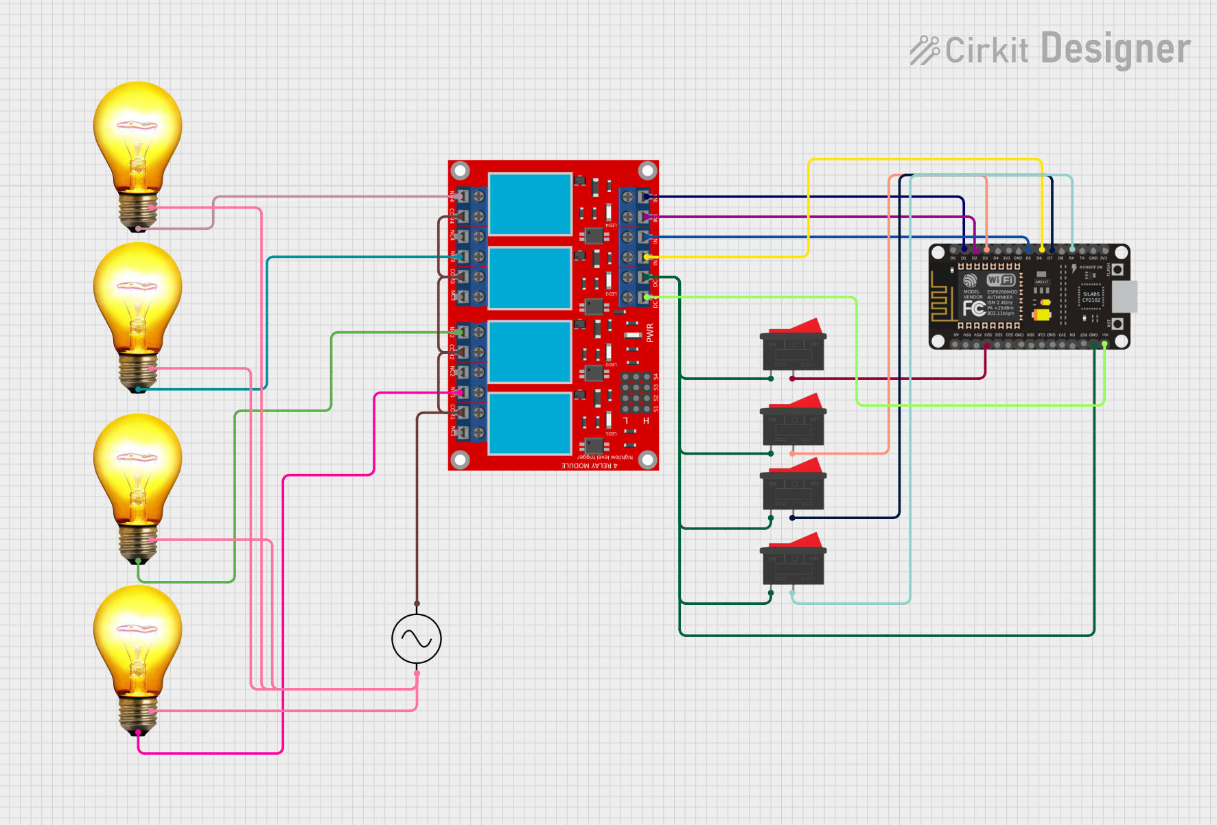
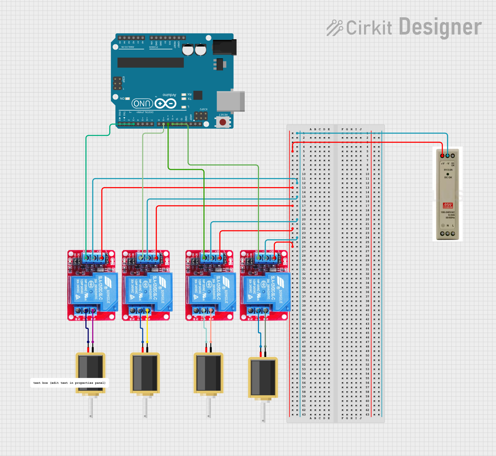
Connecting to a Circuit

  1. Connect the VCC pin to a 5V supply from the microcontroller board.
  2. Connect the GND pin to the common ground of the system.
  3. Connect the IN1, IN2, IN3, and IN4 pins to the digital output pins of the microcontroller.
  4. Connect the high-power AC load to the output terminals of each channel.

Best Practices

  • Ensure that the load does not exceed the specified maximum current rating.
  • Use proper heat dissipation methods if operating near the maximum current rating.
  • Always ensure that the AC power is disconnected before making any connections to the output terminals.
  • Use appropriate wire gauge for the AC side to handle the current without overheating.

Example Code for Arduino UNO

// Define the control pins for the SSR channels
const int ssrPin1 = 2;
const int ssrPin2 = 3;
const int ssrPin3 = 4;
const int ssrPin4 = 5;

void setup() {
  // Set the digital pins as outputs
  pinMode(ssrPin1, OUTPUT);
  pinMode(ssrPin2, OUTPUT);
  pinMode(ssrPin3, OUTPUT);
  pinMode(ssrPin4, OUTPUT);
}

void loop() {
  // Turn on each SSR channel for 1 second, then off for 1 second
  digitalWrite(ssrPin1, HIGH);
  delay(1000);
  digitalWrite(ssrPin1, LOW);
  
  digitalWrite(ssrPin2, HIGH);
  delay(1000);
  digitalWrite(ssrPin2, LOW);
  
  digitalWrite(ssrPin3, HIGH);
  delay(1000);
  digitalWrite(ssrPin3, LOW);
  
  digitalWrite(ssrPin4, HIGH);
  delay(1000);
  digitalWrite(ssrPin4, LOW);
  
  // Repeat the cycle
  delay(1000);
}

Troubleshooting and FAQs

Common Issues

  • SSR Not Activating: Check the input control voltage and connections. Ensure that the control signal is within the specified range.
  • Overheating: Ensure that the current through the SSR does not exceed the rated value. Check for adequate heat dissipation.
  • Unexpected Behavior: Verify that the zero-crossing feature is suitable for the type of load being controlled.

FAQs

Q: Can I use the SSR module with a DC load? A: This SSR module is designed for AC loads. Using it with a DC load may damage the module.

Q: Is it necessary to use a heat sink with the SSR? A: It depends on the current being switched and the ambient temperature. If operating near the maximum rating, a heat sink is recommended.

Q: Can I control the SSR module with a 3.3V logic level? A: Yes, the input control voltage range typically allows for 3.3V logic levels, but always check the specifications of your particular module.

Q: How do I know if the SSR is on or off? A: Some SSR modules have an LED indicator for each channel. If the LED is on, the corresponding relay channel is activated.

Remember to always follow safety precautions when working with high voltage and consult a professional if you are unsure about any aspect of working with electrical components.