Cirkit Designer Logo
Cirkit Designer
Your all-in-one circuit design IDE
Home / 
Component Documentation

How to Use GPIO Screw Terminal Hat: Examples, Pinouts, and Specs

Image of GPIO Screw Terminal Hat
Cirkit Designer LogoDesign with GPIO Screw Terminal Hat in Cirkit Designer

Introduction

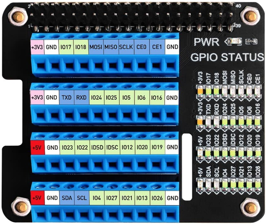
The GPIO Screw Terminal Hat, manufactured by GeeekPi (Part ID: B08GKQMC72), is an add-on board designed to simplify connections to the GPIO pins of single-board computers like the Raspberry Pi. It provides screw terminal connections for each GPIO pin, enabling secure and reliable wiring for external devices, sensors, and modules. This hat is particularly useful for prototyping, educational projects, and applications requiring robust connections.

Explore Projects Built with GPIO Screw Terminal Hat

Use Cirkit Designer to design, explore, and prototype these projects online. Some projects support real-time simulation. Click "Open Project" to start designing instantly!
Pushbutton Interface with General Purpose I/O Plug
Image of Assista GP IO: A project utilizing GPIO Screw Terminal Hat in a practical application
This circuit consists of a General Purpose Input/Output (GPIO) plug connected to four pushbuttons. Each pushbutton is wired to a unique input pin on the GPIO plug, allowing the state of each button (pressed or not pressed) to be detected individually. The common terminals of the pushbuttons are interconnected and likely serve as a ground or reference voltage connection.
Cirkit Designer LogoOpen Project in Cirkit Designer
Raspberry Pi 4B-Based Multi-Sensor Interface Hub with GPS and GSM
Image of Rocket: A project utilizing GPIO Screw Terminal Hat in a practical application
This circuit features a Raspberry Pi 4B interfaced with an IMX296 color global shutter camera, a Neo 6M GPS module, an Adafruit BMP388 barometric pressure sensor, an MPU-6050 accelerometer/gyroscope, and a Sim800l GSM module for cellular connectivity. Power management is handled by an MT3608 boost converter, which steps up the voltage from a Lipo battery, with a resettable fuse PTC and a 1N4007 diode for protection. The Adafruit Perma-Proto HAT is used for organizing connections and interfacing the sensors and modules with the Raspberry Pi via I2C and GPIO pins.
Cirkit Designer LogoOpen Project in Cirkit Designer
High Voltage Generator with Push Switch Activation
Image of Women Safety Device : A project utilizing GPIO Screw Terminal Hat in a practical application
This circuit features a high voltage generator connected to a terminal PCB for output, with its power supply controlled by a 2-pin push switch. The high voltage generator's VCC is connected through the switch, allowing the user to turn the high voltage output on and off. The circuit is powered by a 7.4V battery, with the positive terminal connected to the switch and the negative terminal connected to the generator's ground.
Cirkit Designer LogoOpen Project in Cirkit Designer
Raspberry Pi 5 and TTL Serial JPEG Camera for Image Capture
Image of coe333: A project utilizing GPIO Screw Terminal Hat in a practical application
This circuit connects a TTL Serial JPEG Camera to a Raspberry Pi 5, enabling the Raspberry Pi to receive image data from the camera via UART communication. The camera's GND, RX, and TX pins are connected to the Raspberry Pi's GND, GPIO 14, and GPIO 15 pins, respectively.
Cirkit Designer LogoOpen Project in Cirkit Designer

Explore Projects Built with GPIO Screw Terminal Hat

Use Cirkit Designer to design, explore, and prototype these projects online. Some projects support real-time simulation. Click "Open Project" to start designing instantly!
Image of Assista GP IO: A project utilizing GPIO Screw Terminal Hat in a practical application
Pushbutton Interface with General Purpose I/O Plug
This circuit consists of a General Purpose Input/Output (GPIO) plug connected to four pushbuttons. Each pushbutton is wired to a unique input pin on the GPIO plug, allowing the state of each button (pressed or not pressed) to be detected individually. The common terminals of the pushbuttons are interconnected and likely serve as a ground or reference voltage connection.
Cirkit Designer LogoOpen Project in Cirkit Designer
Image of Rocket: A project utilizing GPIO Screw Terminal Hat in a practical application
Raspberry Pi 4B-Based Multi-Sensor Interface Hub with GPS and GSM
This circuit features a Raspberry Pi 4B interfaced with an IMX296 color global shutter camera, a Neo 6M GPS module, an Adafruit BMP388 barometric pressure sensor, an MPU-6050 accelerometer/gyroscope, and a Sim800l GSM module for cellular connectivity. Power management is handled by an MT3608 boost converter, which steps up the voltage from a Lipo battery, with a resettable fuse PTC and a 1N4007 diode for protection. The Adafruit Perma-Proto HAT is used for organizing connections and interfacing the sensors and modules with the Raspberry Pi via I2C and GPIO pins.
Cirkit Designer LogoOpen Project in Cirkit Designer
Image of Women Safety Device : A project utilizing GPIO Screw Terminal Hat in a practical application
High Voltage Generator with Push Switch Activation
This circuit features a high voltage generator connected to a terminal PCB for output, with its power supply controlled by a 2-pin push switch. The high voltage generator's VCC is connected through the switch, allowing the user to turn the high voltage output on and off. The circuit is powered by a 7.4V battery, with the positive terminal connected to the switch and the negative terminal connected to the generator's ground.
Cirkit Designer LogoOpen Project in Cirkit Designer
Image of coe333: A project utilizing GPIO Screw Terminal Hat in a practical application
Raspberry Pi 5 and TTL Serial JPEG Camera for Image Capture
This circuit connects a TTL Serial JPEG Camera to a Raspberry Pi 5, enabling the Raspberry Pi to receive image data from the camera via UART communication. The camera's GND, RX, and TX pins are connected to the Raspberry Pi's GND, GPIO 14, and GPIO 15 pins, respectively.
Cirkit Designer LogoOpen Project in Cirkit Designer

Common Applications and Use Cases

  • Prototyping circuits with Raspberry Pi or other single-board computers
  • Connecting sensors, actuators, and external modules
  • Educational projects for learning GPIO pin usage
  • Industrial or semi-permanent installations requiring secure wiring
  • Projects requiring frequent reconfiguration of connections

Technical Specifications

The GPIO Screw Terminal Hat is designed to interface seamlessly with the GPIO header of a Raspberry Pi or similar devices. Below are the key technical details:

Key Specifications

  • Manufacturer: GeeekPi
  • Part ID: B08GKQMC72
  • Compatible Devices: Raspberry Pi (all models with 40-pin GPIO header)
  • Number of Terminals: 40 screw terminals (1 per GPIO pin)
  • Voltage Range: 3.3V to 5V (dependent on the GPIO pin voltage)
  • Current Rating: Up to 2A per terminal
  • Material: PCB with durable screw terminals
  • Dimensions: Matches Raspberry Pi form factor
  • Mounting: Directly plugs into the 40-pin GPIO header

Pin Configuration and Descriptions

The GPIO Screw Terminal Hat maps each GPIO pin to a corresponding screw terminal. Below is the pin configuration:

GPIO Pin Screw Terminal Label Functionality (Default)
1 3.3V Power (3.3V)
2 5V Power (5V)
3 GPIO2 (SDA1) I2C Data
4 5V Power (5V)
5 GPIO3 (SCL1) I2C Clock
6 GND Ground
7 GPIO4 General Purpose I/O
8 GPIO14 (TXD) UART Transmit
9 GND Ground
10 GPIO15 (RXD) UART Receive
... ... ...
39 GND Ground
40 GPIO21 General Purpose I/O

Note: The full pinout follows the Raspberry Pi GPIO header standard. Refer to the Raspberry Pi GPIO documentation for detailed pin functionality.

Usage Instructions

How to Use the GPIO Screw Terminal Hat

  1. Attach the Hat: Align the GPIO Screw Terminal Hat with the 40-pin GPIO header on your Raspberry Pi and gently press it down until it is securely connected.
  2. Connect Wires: Insert the stripped end of a wire into the desired screw terminal and tighten the screw to secure the connection.
  3. Power the Raspberry Pi: Ensure the Raspberry Pi is powered off before connecting the hat. Once all connections are secure, power on the Raspberry Pi.
  4. Program the GPIO Pins: Use a programming language like Python to control the GPIO pins. For example, the RPi.GPIO library can be used to configure and control the pins.

Example Code for Raspberry Pi

Below is an example Python script to blink an LED connected to GPIO17 (screw terminal labeled GPIO17):

import RPi.GPIO as GPIO
import time

Set up GPIO mode and pin

GPIO.setmode(GPIO.BCM) # Use Broadcom pin numbering GPIO.setup(17, GPIO.OUT) # Set GPIO17 as an output pin

try: while True: GPIO.output(17, GPIO.HIGH) # Turn LED on time.sleep(1) # Wait for 1 second GPIO.output(17, GPIO.LOW) # Turn LED off time.sleep(1) # Wait for 1 second except KeyboardInterrupt: # Clean up GPIO settings on exit GPIO.cleanup()


> **Important**: Always ensure the GPIO pin voltage and current ratings are not exceeded to avoid damaging the Raspberry Pi or connected components.

Best Practices

  • Double-check connections to ensure wires are securely fastened in the screw terminals.
  • Avoid connecting high-current or high-voltage devices directly to GPIO pins.
  • Use external relays or transistors for controlling high-power devices.
  • Power off the Raspberry Pi before attaching or detaching the hat.

Troubleshooting and FAQs

Common Issues and Solutions

  1. Loose Connections

    • Issue: Wires are not securely fastened in the screw terminals.
    • Solution: Ensure the screws are tightened properly, and the wire is stripped to the correct length.
  2. GPIO Pin Not Responding

    • Issue: Incorrect pin numbering in the code.
    • Solution: Verify the pin numbering (BCM vs. BOARD) in your code matches the physical pin layout.
  3. Overheating or Damage

    • Issue: Excessive current or voltage applied to GPIO pins.
    • Solution: Use current-limiting resistors and ensure the connected devices are within the GPIO pin specifications.
  4. Hat Not Detected

    • Issue: Hat not properly seated on the GPIO header.
    • Solution: Power off the Raspberry Pi, reseat the hat, and ensure all pins are aligned.

FAQs

  • Can I use this hat with other single-board computers?
    Yes, as long as the device has a compatible 40-pin GPIO header and similar pinout.

  • What wire gauge is supported by the screw terminals?
    The screw terminals typically support wire gauges from 26 AWG to 18 AWG.

  • Can I stack other hats on top of this one?
    No, this hat does not support stacking due to the screw terminal design.

  • Is the hat compatible with 3.3V and 5V logic?
    Yes, the hat supports both 3.3V and 5V logic levels, depending on the GPIO pin configuration.

By following this documentation, you can effectively use the GPIO Screw Terminal Hat for your projects and ensure reliable connections to your Raspberry Pi GPIO pins.