
How to Use scc: Examples, Pinouts, and Specs
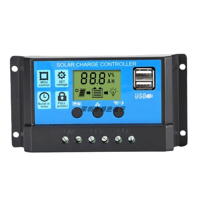
 Design with scc in Cirkit Designer
Introduction
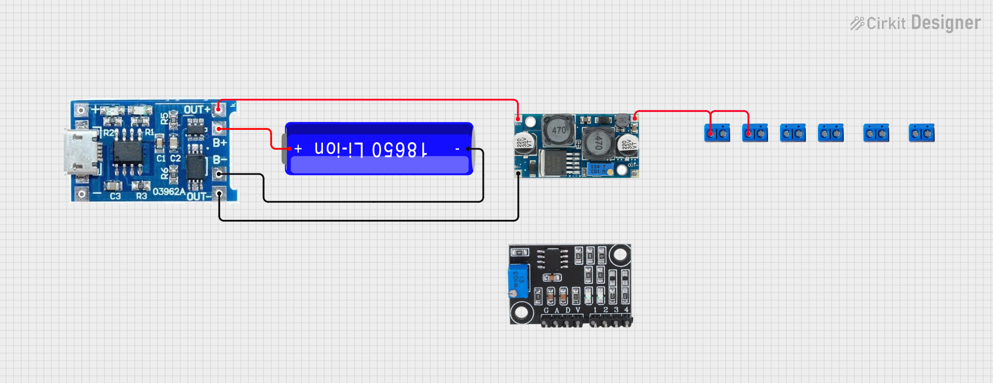
The Signal Conditioning Circuit (SCC), manufactured by Cina (Part ID: SCC), is a versatile electronic component designed to modify and prepare signals for further processing. It is commonly used to amplify, filter, or convert signals into a format suitable for subsequent stages in a system, such as analog-to-digital conversion or data acquisition.
Explore Projects Built with scc
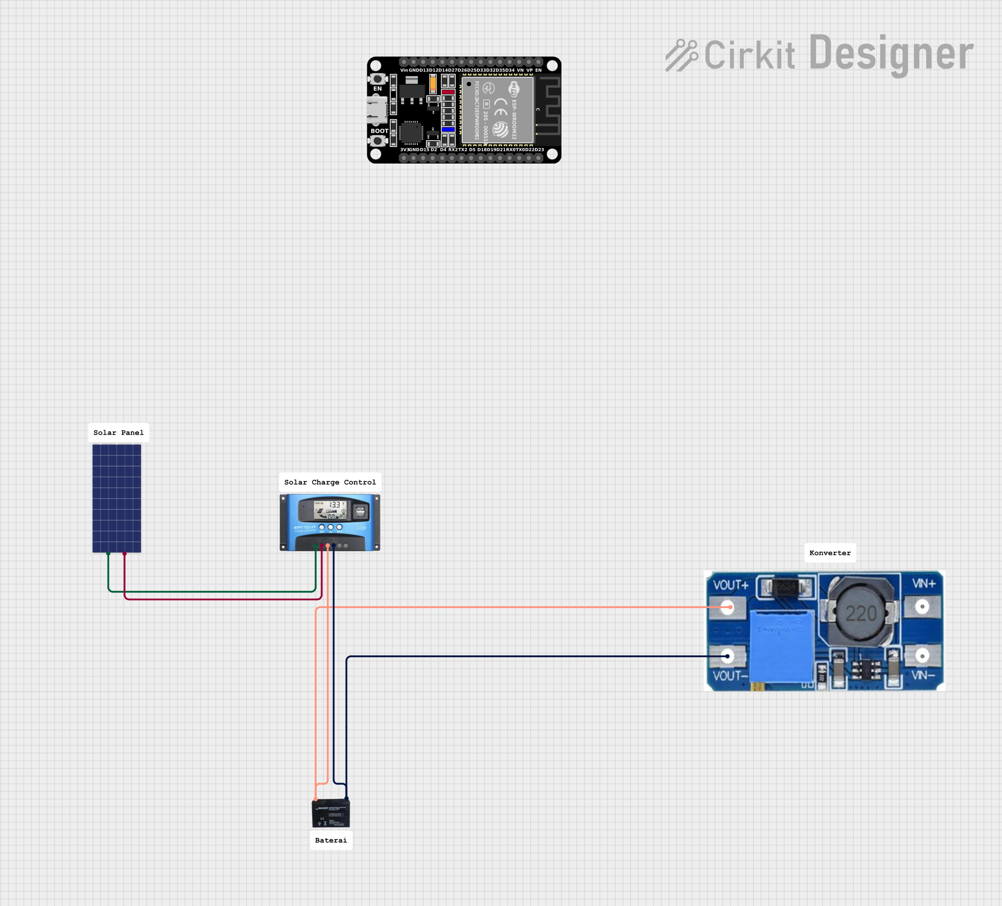
 Open Project in Cirkit Designer
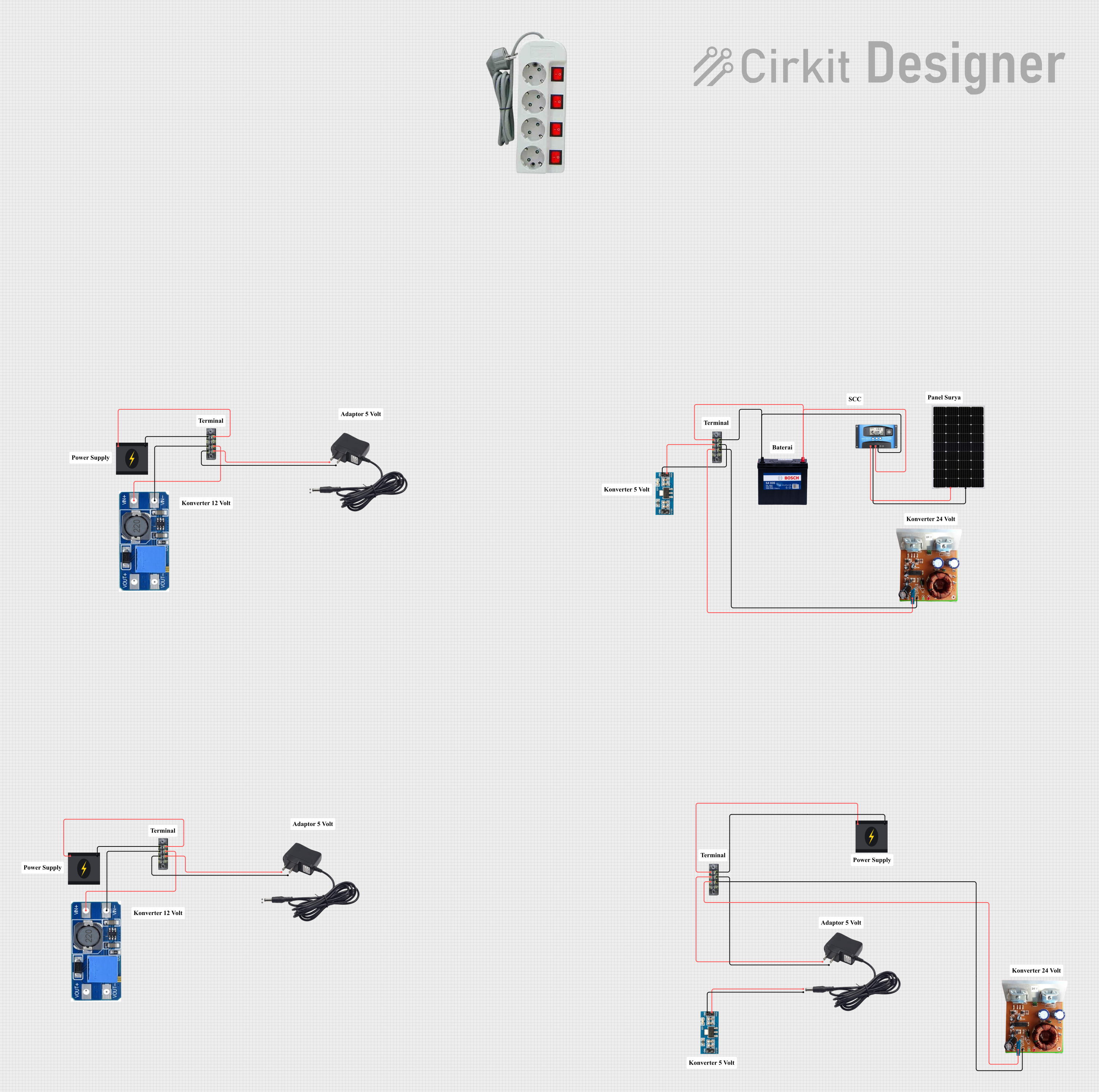
 Open Project in Cirkit Designer
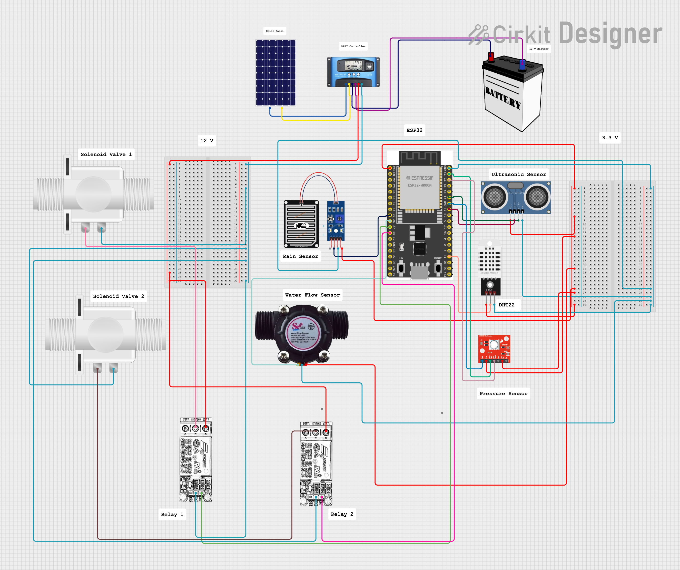
 Open Project in Cirkit Designer
 Open Project in Cirkit Designer
Explore Projects Built with scc

 Open Project in Cirkit Designer
 Open Project in Cirkit Designer
 Open Project in Cirkit Designer
 Open Project in Cirkit Designer
Common Applications and Use Cases
- Sensor Signal Processing: Amplifying weak signals from sensors like thermocouples, strain gauges, or photodiodes.
- Filtering: Removing noise or unwanted frequency components from signals.
- Analog-to-Digital Conversion (ADC): Preparing signals for ADC by scaling and offsetting.
- Industrial Automation: Conditioning signals from industrial sensors for control systems.
- Medical Devices: Processing bio-signals such as ECG or EEG for monitoring and analysis.
Technical Specifications
Key Technical Details
| Parameter | Value |
|---|---|
| Supply Voltage (Vcc) | 3.3V to 5V |
| Input Signal Range | ±10 mV to ±10 V |
| Output Signal Range | 0V to 5V |
| Gain | Programmable (1x to 100x) |
| Bandwidth | DC to 100 kHz |
| Input Impedance | >1 MΩ |
| Output Impedance | <100 Ω |
| Operating Temperature | -40°C to +85°C |
| Package Type | DIP-8 or SOIC-8 |
Pin Configuration and Descriptions
| Pin Number | Pin Name | Description |
|---|---|---|
| 1 | Vcc | Positive power supply (3.3V to 5V). |
| 2 | GND | Ground connection. |
| 3 | IN+ | Non-inverting input for the signal to be conditioned. |
| 4 | IN- | Inverting input for the signal to be conditioned. |
| 5 | GAIN_SEL | Gain selection pin. Connect to GND, Vcc, or external resistor to set gain. |
| 6 | OUT | Conditioned output signal. |
| 7 | FILTER_SEL | Filter selection pin. Connect to external capacitor for custom filtering. |
| 8 | NC | No connection. Leave unconnected or use for mechanical stability. |
Usage Instructions
How to Use the SCC in a Circuit
- Power Supply: Connect the Vcc pin to a stable 3.3V or 5V power source and the GND pin to the ground.
- Input Signal: Connect the signal source to the IN+ and IN- pins. For single-ended signals, connect IN- to GND.
- Gain Configuration: Use the GAIN_SEL pin to set the desired gain:
- Connect to GND for 1x gain.
- Connect to Vcc for 10x gain.
- Use an external resistor for custom gain values (refer to the datasheet for resistor values).
- Filtering: Attach an external capacitor to the FILTER_SEL pin to implement custom low-pass filtering. For no filtering, leave this pin unconnected.
- Output Signal: The conditioned signal will be available at the OUT pin. Connect this to the next stage of your circuit, such as an ADC or microcontroller.
Important Considerations and Best Practices
- Input Signal Range: Ensure the input signal does not exceed the specified range (±10 mV to ±10 V) to avoid distortion or damage.
- Power Supply Decoupling: Place a 0.1 µF ceramic capacitor close to the Vcc pin to reduce noise and ensure stable operation.
- Gain and Filtering: Select appropriate gain and filtering settings based on your application to optimize performance.
- Temperature Range: Operate the SCC within the specified temperature range (-40°C to +85°C) for reliable performance.
Example: Connecting SCC to an Arduino UNO
The SCC can be used with an Arduino UNO to condition sensor signals before ADC. Below is an example of how to connect and use the SCC:
Circuit Connections
- Vcc: Connect to the Arduino's 5V pin.
- GND: Connect to the Arduino's GND pin.
- IN+: Connect to the sensor's signal output.
- IN-: Connect to GND (for single-ended signals).
- OUT: Connect to an analog input pin on the Arduino (e.g., A0).
- GAIN_SEL: Connect to GND for 1x gain.
- FILTER_SEL: Leave unconnected for no filtering.
Arduino Code Example
// Arduino code to read the conditioned signal from the SCC
const int analogPin = A0; // Analog pin connected to SCC OUT pin
int sensorValue = 0;      // Variable to store the ADC value

void setup() {
  Serial.begin(9600); // Initialize serial communication at 9600 baud
}

void loop() {
  sensorValue = analogRead(analogPin); // Read the analog value from SCC
  float voltage = sensorValue * (5.0 / 1023.0); // Convert ADC value to voltage
  Serial.print("Conditioned Signal Voltage: ");
  Serial.print(voltage);
  Serial.println(" V");
  delay(500); // Wait for 500 ms before the next reading
}
Troubleshooting and FAQs
Common Issues and Solutions
No Output Signal:
- Verify that the power supply (Vcc and GND) is correctly connected.
- Check the input signal connections (IN+ and IN-).
- Ensure the gain and filter settings are configured properly.
Distorted Output Signal:
- Ensure the input signal is within the specified range (±10 mV to ±10 V).
- Check for noise or instability in the power supply. Add decoupling capacitors if needed.
- Verify that the external components (e.g., resistors, capacitors) are correctly selected and connected.
Output Signal Too Weak or Too Strong:
- Adjust the gain setting using the GAIN_SEL pin.
- Verify that the load connected to the OUT pin does not exceed the output drive capability.
FAQs
Q1: Can the SCC handle AC signals?
A1: Yes, the SCC can process both AC and DC signals within the specified input range.
Q2: How do I implement a custom filter?
A2: Connect an appropriately valued capacitor to the FILTER_SEL pin. Refer to the datasheet for recommended capacitor values based on the desired cutoff frequency.
Q3: Can I use the SCC with a 3.3V system?
A3: Yes, the SCC is compatible with both 3.3V and 5V systems. Ensure the input and output signals are within the specified ranges for the chosen supply voltage.
Q4: What is the maximum output current of the SCC?
A4: The SCC can drive loads with an impedance of 100 Ω or higher. For lower impedance loads, use a buffer or amplifier.