How to Use TPS22917 Load Driver/Power Switch: Examples, Pinouts, and Specs
Introduction
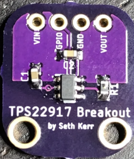
The TPS22917 is a load driver and power switch designed to provide controlled power delivery to a load. Manufactured under part ID TPS22917, this component features low on-resistance, fast switching times, and built-in protection mechanisms such as overcurrent protection and thermal shutdown. These features make it highly reliable and efficient for power management applications.
Explore Projects Built with TPS22917 Load Driver/Power Switch


Explore Projects Built with TPS22917 Load Driver/Power Switch
Common Applications and Use Cases
- Power distribution in portable devices
- Battery-powered systems
- Consumer electronics
- Industrial and automotive power management
- Load switching in microcontroller-based systems
Technical Specifications
Key Technical Details
| Parameter | Value |
|---|---|
| Input Voltage Range | 1 V to 5.5 V |
| On-Resistance (RON) | 16 mΩ (typical at 5 V input) |
| Maximum Continuous Current | 2 A |
| Quiescent Current (IQ) | 19 µA (typical) |
| Shutdown Current (ISD) | 0.5 µA (typical) |
| Enable Voltage Threshold | 0.85 V (logic high) |
| Turn-On Time | 85 µs (typical at 5 V input) |
| Protection Features | Overcurrent, thermal shutdown |
| Package Options | SOT-23-6, WSON-6 |
Pin Configuration and Descriptions
SOT-23-6 Package Pinout
| Pin Number | Pin Name | Description |
|---|---|---|
| 1 | VIN | Input voltage supply (1 V to 5.5 V) |
| 2 | GND | Ground connection |
| 3 | EN | Enable pin (active high) |
| 4 | NC | No connection (leave floating or connect to GND) |
| 5 | VOUT | Output voltage to the load |
| 6 | FLT | Fault indicator (open-drain, active low) |
WSON-6 Package Pinout
| Pin Number | Pin Name | Description |
|---|---|---|
| 1 | VIN | Input voltage supply (1 V to 5.5 V) |
| 2 | GND | Ground connection |
| 3 | EN | Enable pin (active high) |
| 4 | FLT | Fault indicator (open-drain, active low) |
| 5 | VOUT | Output voltage to the load |
| 6 | NC | No connection (leave floating or connect to GND) |
Usage Instructions
How to Use the TPS22917 in a Circuit
- Power Supply Connection: Connect the input voltage (VIN) to a regulated power source within the range of 1 V to 5.5 V. Ensure the power source can supply sufficient current for the load.
- Enable Pin (EN): Drive the EN pin high (above 0.85 V) to turn on the switch. Pull the EN pin low to disable the switch and disconnect the load.
- Output Connection: Connect the load to the VOUT pin. Ensure the load does not exceed the maximum continuous current rating of 2 A.
- Fault Indicator (FLT): Use the FLT pin to monitor fault conditions. This pin is open-drain and will pull low when a fault (e.g., overcurrent or thermal shutdown) occurs. Use a pull-up resistor (e.g., 10 kΩ) to connect FLT to the desired logic level.
- Bypass Capacitor: Place a bypass capacitor (e.g., 1 µF) close to the VIN pin to stabilize the input voltage and reduce noise.
Important Considerations and Best Practices
- Thermal Management: Ensure adequate heat dissipation, especially when operating near the maximum current rating. Use a PCB with good thermal conductivity or add heat sinks if necessary.
- Overcurrent Protection: The TPS22917 includes built-in overcurrent protection. However, avoid designing circuits that consistently operate near the current limit to prevent frequent fault conditions.
- Enable Pin Logic Levels: Ensure the EN pin voltage meets the logic high threshold (0.85 V or higher) to enable the switch. For microcontroller-based systems, connect the EN pin to a GPIO pin.
- Fault Handling: If a fault condition occurs, investigate the cause (e.g., excessive load current or overheating) and resolve it before re-enabling the switch.
Example: Connecting the TPS22917 to an Arduino UNO
The following example demonstrates how to control the TPS22917 using an Arduino UNO. The EN pin is connected to a GPIO pin on the Arduino to enable or disable the switch.
Circuit Diagram
- VIN: Connect to a 5 V power supply.
- VOUT: Connect to the load (e.g., an LED or motor).
- EN: Connect to Arduino digital pin 7.
- GND: Connect to the common ground of the circuit.
- FLT: Connect to Arduino digital pin 8 (optional, for fault monitoring).
Arduino Code
// Define pin connections
const int enablePin = 7; // EN pin connected to digital pin 7
const int faultPin = 8;  // FLT pin connected to digital pin 8 (optional)

void setup() {
  // Set up the enable pin as an output
  pinMode(enablePin, OUTPUT);

  // Set up the fault pin as an input with pull-up resistor
  pinMode(faultPin, INPUT_PULLUP);

  // Initially disable the switch
  digitalWrite(enablePin, LOW);
}

void loop() {
  // Enable the switch
  digitalWrite(enablePin, HIGH);
  delay(1000); // Keep the switch on for 1 second

  // Check for fault condition
  if (digitalRead(faultPin) == LOW) {
    // Fault detected, take appropriate action
    Serial.println("Fault detected! Disabling switch.");
    digitalWrite(enablePin, LOW);
    while (1); // Halt execution
  }

  // Disable the switch
  digitalWrite(enablePin, LOW);
  delay(1000); // Keep the switch off for 1 second
}
Troubleshooting and FAQs
Common Issues and Solutions
Switch Does Not Turn On
- Cause: EN pin voltage is too low.
- Solution: Ensure the EN pin is driven high (above 0.85 V). Check the GPIO pin configuration if using a microcontroller.
Fault Pin Stays Low
- Cause: Overcurrent or thermal shutdown condition.
- Solution: Reduce the load current or improve thermal management. Check for short circuits on the output.
High Power Dissipation
- Cause: Excessive current or poor thermal design.
- Solution: Ensure the load current is within the specified range. Use a PCB with good thermal conductivity.
Output Voltage is Unstable
- Cause: Insufficient bypass capacitance.
- Solution: Add a bypass capacitor (e.g., 1 µF) close to the VIN pin.
FAQs
Q: Can the TPS22917 handle inductive loads?
A: Yes, but you should add a flyback diode across the load to protect the switch from voltage spikes.Q: What happens if the input voltage exceeds 5.5 V?
A: The device may be damaged. Always ensure the input voltage stays within the specified range.Q: Can I leave the FLT pin unconnected?
A: Yes, the FLT pin is optional. However, connecting it to a pull-up resistor allows you to monitor fault conditions.Q: Is the TPS22917 suitable for battery-powered applications?
A: Yes, its low quiescent current (19 µA typical) makes it ideal for battery-powered systems.