How to Use TRRS 3.5mm Jack Breakout: Examples, Pinouts, and Specs
Introduction
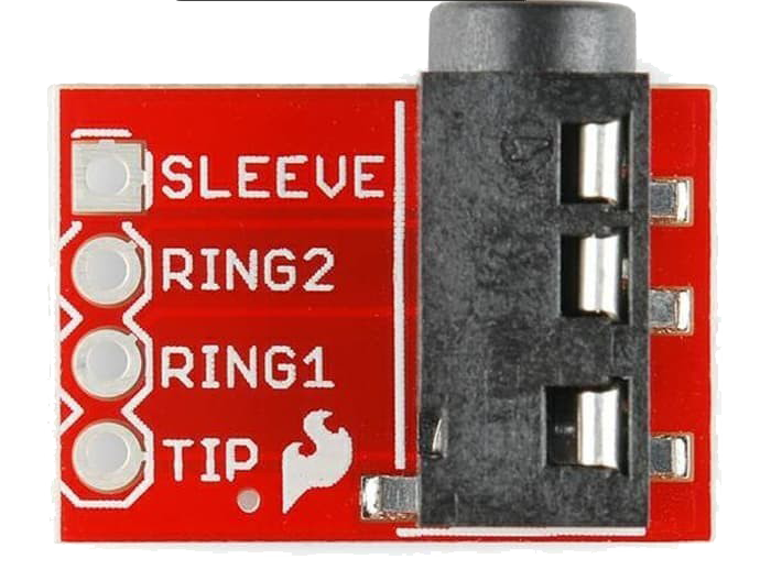
The TRRS 3.5mm Jack Breakout is a versatile and compact electronic component that simplifies the integration of a standard 3.5mm TRRS audio jack into electronic projects. TRRS stands for Tip, Ring, Ring, Sleeve, which refers to the four conductive parts of the jack that are used to transmit audio and control signals. This breakout board is commonly used in audio applications, such as connecting headphones, microphones, or auxiliary audio inputs to electronic devices like MP3 players, smartphones, and computers. It can also be used for serial communications or for adding external controls to a device.
Explore Projects Built with TRRS 3.5mm Jack Breakout
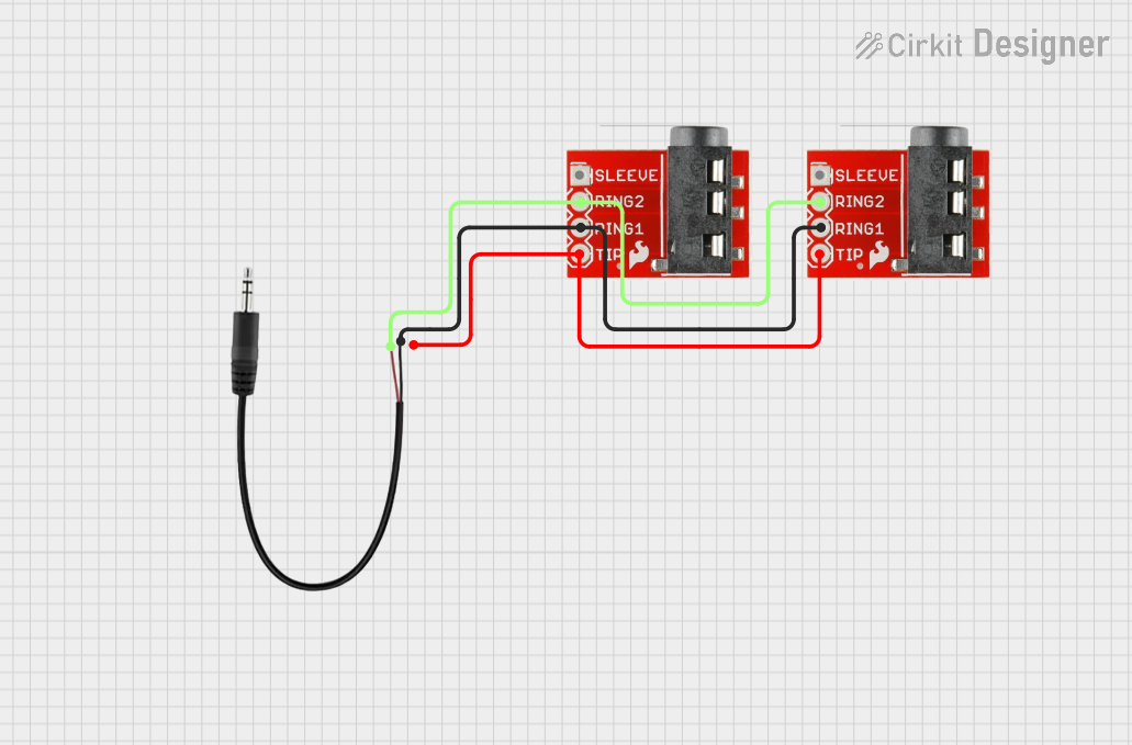
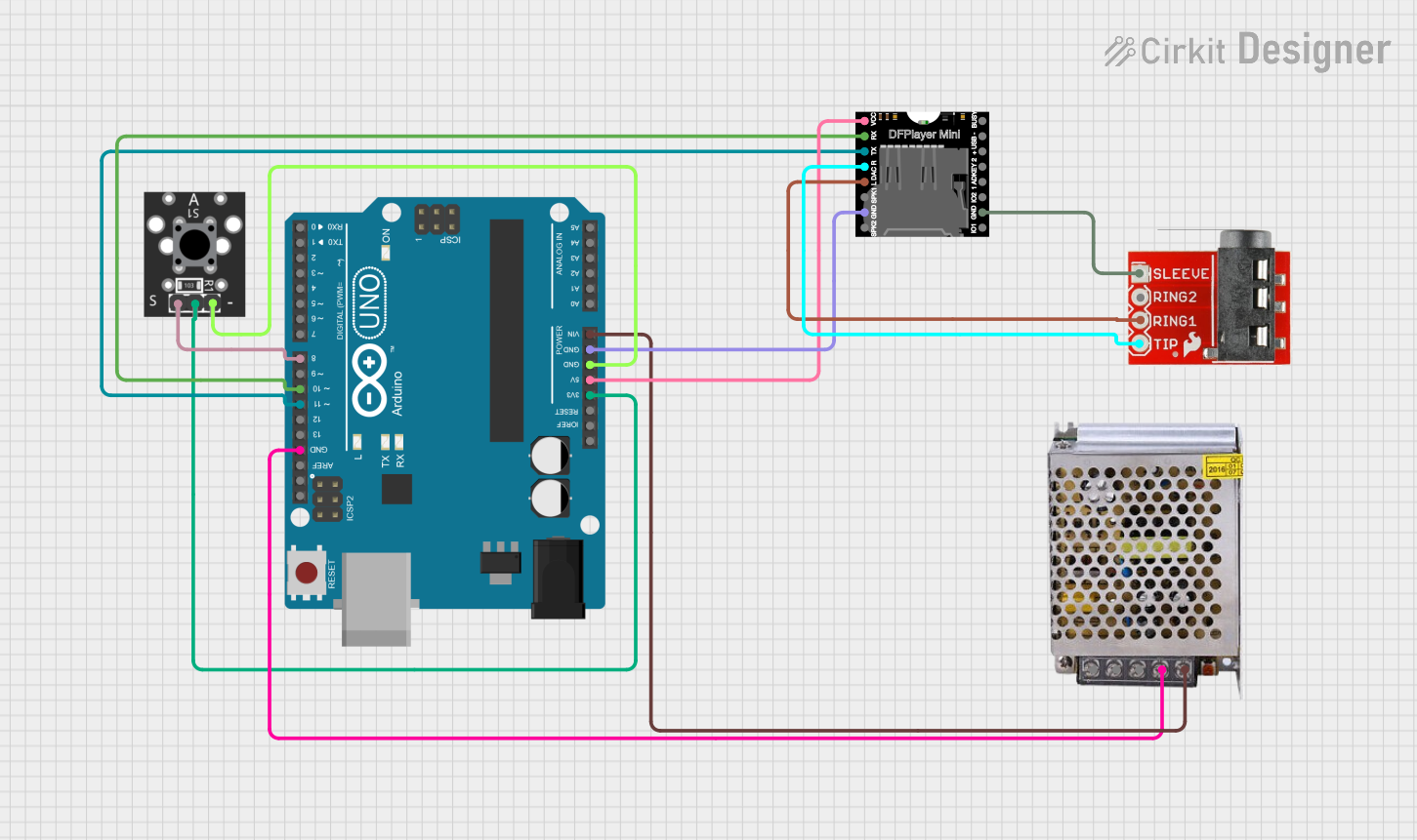


Explore Projects Built with TRRS 3.5mm Jack Breakout
Technical Specifications
Key Technical Details
- Rated Voltage: 5V (typical for logic level compatibility)
- Rated Current: 1A (max per contact)
- Contact Resistance: ≤ 30 mΩ
- Insulation Resistance: ≥ 100 MΩ
- Durability: 5,000 insertion/removal cycles
Pin Configuration and Descriptions
| Pin Name | Description |
|---|---|
| T | Tip - Left audio signal |
| R1 | First Ring - Right audio signal |
| R2 | Second Ring - Ground or microphone |
| S | Sleeve - Ground for audio signals |
Usage Instructions
Integration into a Circuit
To use the TRRS 3.5mm Jack Breakout in a circuit, follow these steps:
- Mounting: Secure the breakout board onto your project's surface or breadboard.
- Wiring: Connect the breakout pins to your circuit according to the pin descriptions. Ensure that the audio signals are correctly matched to the corresponding channels.
- Signal Routing: Route the audio signals to amplifiers, ADCs, or other processing units as required by your application.
- Grounding: Connect the ground pin (S) to the common ground in your circuit to prevent noise and ensure signal integrity.
Best Practices
- Use shielded cables for audio connections to minimize interference.
- Keep audio signal paths as short as possible to reduce potential noise pickup.
- Avoid running audio signal lines parallel to high-current traces to prevent crosstalk.
- Ensure that the breakout board is firmly mounted to prevent intermittent connections.
Troubleshooting and FAQs
Common Issues
- No Audio Output: Check that the connections are secure and that the audio source is functioning. Verify that the signals are routed to the correct pins.
- Intermittent Audio: Inspect the solder joints and cable connections for any loose or broken connections.
- Noise in Audio: Ensure that the ground connections are secure. Use shielded cables and keep audio lines away from sources of electromagnetic interference.
FAQs
Q: Can I use this breakout with a TRS (Tip-Ring-Sleeve) connector? A: Yes, but you will only be able to access the left and right audio channels and the ground. The second ring will not be used.
Q: Is this breakout board compatible with stereo and microphone signals? A: Yes, the TRRS configuration supports both stereo audio and microphone signals, depending on how the source device is wired.
Q: How do I connect a microphone using this breakout? A: Connect the microphone signal to the second ring (R2) and the ground to the sleeve (S).
Example Code for Arduino UNO
Below is an example of how to use the TRRS 3.5mm Jack Breakout to read an analog signal from a microphone connected to an Arduino UNO. This code assumes that the microphone signal is connected to the second ring (R2) and the ground to the sleeve (S).
// Define the analog pin connected to the microphone signal
const int micPin = A0;

void setup() {
  // Initialize serial communication at 9600 baud rate
  Serial.begin(9600);
}

void loop() {
  // Read the analog value from the microphone
  int micValue = analogRead(micPin);

  // Print the value to the Serial Monitor
  Serial.println(micValue);

  // Wait for a short period before reading again
  delay(10);
}
Remember to adjust the micPin variable to match the actual analog pin used in your setup. This code will output the raw analog values from the microphone to the Serial Monitor, which can be used for further processing or visualization.