Cirkit Designer
Your all-in-one circuit design IDE
Home /
Component Documentation
How to Use TEA5767: Examples, Pinouts, and Specs
Introduction
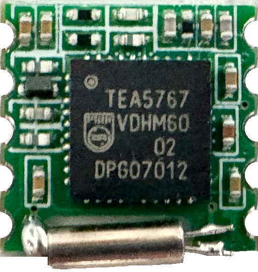
The TEA5767 is a single-chip electronically tuned FM stereo radio designed for low-voltage applications. Manufactured by Phillips, this component integrates IF selectivity and demodulation, making it a compact and efficient solution for FM radio reception. It is widely used in portable audio devices, mobile phones, and other consumer electronics where space and power efficiency are critical.
Explore Projects Built with TEA5767
ESP32 and TEA5767 FM Radio with ILI9341 Display and Potentiometer Tuning
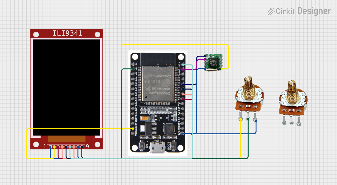
This circuit is an FM radio receiver with a TEA5767 tuner module controlled by an ESP32 microcontroller. The ESP32 reads the frequency input from a rotary potentiometer and displays the current frequency on an ILI9341 TFT display. The microcontroller adjusts the tuner frequency via I2C communication based on the potentiometer's position.
Arduino Nano 33 BLE Battery-Powered Display Interface

This circuit features a Nano 33 BLE microcontroller interfaced with a TM1637 4-digit 7-segment display for information output, powered by a 3.7V battery managed by a TP4056 charging module. The microcontroller communicates with the display to present data, while the TP4056 ensures the battery is charged safely and provides power to the system.
RTL8720DN-Based Interactive Button-Controlled TFT Display

This circuit features an RTL8720DN microcontroller interfaced with a China ST7735S 160x128 TFT LCD display and four pushbuttons. The microcontroller reads the states of the pushbuttons and displays their statuses on the TFT LCD, providing a visual feedback system for button presses.
Teensy 4.0 and MAX7219-Based 7-Segment Display Counter

This circuit uses a Teensy 4.0 microcontroller to control a MAX7219 LED driver, which in turn drives three 7-segment displays. The microcontroller runs code to display numbers from 0 to 999 on the 7-segment displays, with the SN74AHCT125N buffer providing signal integrity and the necessary capacitors and resistors ensuring stable operation.
Explore Projects Built with TEA5767
ESP32 and TEA5767 FM Radio with ILI9341 Display and Potentiometer Tuning
This circuit is an FM radio receiver with a TEA5767 tuner module controlled by an ESP32 microcontroller. The ESP32 reads the frequency input from a rotary potentiometer and displays the current frequency on an ILI9341 TFT display. The microcontroller adjusts the tuner frequency via I2C communication based on the potentiometer's position.
Arduino Nano 33 BLE Battery-Powered Display Interface
This circuit features a Nano 33 BLE microcontroller interfaced with a TM1637 4-digit 7-segment display for information output, powered by a 3.7V battery managed by a TP4056 charging module. The microcontroller communicates with the display to present data, while the TP4056 ensures the battery is charged safely and provides power to the system.
RTL8720DN-Based Interactive Button-Controlled TFT Display
This circuit features an RTL8720DN microcontroller interfaced with a China ST7735S 160x128 TFT LCD display and four pushbuttons. The microcontroller reads the states of the pushbuttons and displays their statuses on the TFT LCD, providing a visual feedback system for button presses.
Teensy 4.0 and MAX7219-Based 7-Segment Display Counter
This circuit uses a Teensy 4.0 microcontroller to control a MAX7219 LED driver, which in turn drives three 7-segment displays. The microcontroller runs code to display numbers from 0 to 999 on the 7-segment displays, with the SN74AHCT125N buffer providing signal integrity and the necessary capacitors and resistors ensuring stable operation.
Common Applications and Use Cases
- Portable audio devices
- Mobile phones
- MP3 players
- Personal digital assistants (PDAs)
- Car audio systems
- Home audio systems
Technical Specifications
Key Technical Details
| Parameter | Value |
|---|---|
| Supply Voltage | 2.5V to 5.5V |
| Operating Current | 12 mA (typical) |
| Frequency Range | 76 MHz to 108 MHz |
| Sensitivity | 2.0 µV (typical) |
| Signal-to-Noise Ratio | 60 dB (typical) |
| Stereo Separation | 30 dB (typical) |
| Audio Output Voltage | 75 mV (typical) |
| Package | SOP16 |
Pin Configuration and Descriptions
| Pin No. | Pin Name | Description |
|---|---|---|
| 1 | VCC | Power supply |
| 2 | GND | Ground |
| 3 | SDA | I2C data line |
| 4 | SCL | I2C clock line |
| 5 | MPXOUT | Multiplexed audio output |
| 6 | LOUT | Left audio output |
| 7 | ROUT | Right audio output |
| 8 | VREF | Reference voltage |
| 9 | VCO | Voltage-controlled oscillator |
| 10 | XTAL | Crystal oscillator input |
| 11 | NC | Not connected |
| 12 | NC | Not connected |
| 13 | NC | Not connected |
| 14 | NC | Not connected |
| 15 | NC | Not connected |
| 16 | NC | Not connected |
Usage Instructions
How to Use the TEA5767 in a Circuit
- Power Supply: Connect the VCC pin to a 2.5V to 5.5V power supply and the GND pin to ground.
- I2C Communication: Connect the SDA and SCL pins to the corresponding I2C data and clock lines of your microcontroller.
- Audio Output: Connect the LOUT and ROUT pins to the left and right audio inputs of your audio amplifier or headphones.
- Crystal Oscillator: Connect a 32.768 kHz crystal to the XTAL pin for stable frequency generation.
- Reference Voltage: Connect the VREF pin to a stable reference voltage, typically 1.2V.
Important Considerations and Best Practices
- Decoupling Capacitors: Place decoupling capacitors close to the VCC pin to filter out noise.
- I2C Pull-up Resistors: Use pull-up resistors (typically 4.7kΩ) on the SDA and SCL lines to ensure proper I2C communication.
- Antenna: Connect an appropriate antenna to the VCO pin for better reception.
- Ground Plane: Use a solid ground plane in your PCB design to minimize noise and interference.
Example Code for Arduino UNO
#include <Wire.h>

#define TEA5767_I2C_ADDRESS 0x60

void setup() {
  Wire.begin(); // Initialize I2C communication
  Serial.begin(9600); // Initialize serial communication
  setFrequency(101.1); // Set frequency to 101.1 MHz
}

void loop() {
  // Main loop does nothing
}

void setFrequency(float frequency) {
  uint16_t frequencyB = (4 * (frequency * 1000000 + 225000)) / 32768;
  byte frequencyH = frequencyB >> 8;
  byte frequencyL = frequencyB & 0xFF;

  Wire.beginTransmission(TEA5767_I2C_ADDRESS);
  Wire.write(frequencyH); // Send high byte of frequency
  Wire.write(frequencyL); // Send low byte of frequency
  Wire.write(0xB0); // Set to stereo, mute off
  Wire.write(0x10); // Set to high side LO injection
  Wire.write(0x00); // No software mute, no search mode
  Wire.write(0x00); // No software mute, no search mode
  Wire.endTransmission();
}
Troubleshooting and FAQs
Common Issues Users Might Face
- No Audio Output: Ensure that the audio output pins (LOUT and ROUT) are properly connected to the audio amplifier or headphones.
- Poor Reception: Check the antenna connection and ensure it is properly connected to the VCO pin. Also, verify that the frequency is set correctly.
- I2C Communication Failure: Ensure that the SDA and SCL lines have proper pull-up resistors and that the I2C address is correct.
Solutions and Tips for Troubleshooting
- Check Connections: Verify all connections, especially power supply, ground, and I2C lines.
- Use Decoupling Capacitors: Place decoupling capacitors close to the VCC pin to filter out noise.
- Verify Frequency Setting: Ensure that the frequency is set correctly in the code and that the crystal oscillator is functioning properly.
- Inspect Antenna: Ensure that the antenna is properly connected and positioned for optimal reception.
By following this documentation, users should be able to effectively integrate and utilize the TEA5767 FM stereo radio module in their projects.