
How to Use I2C Thermocouple Amplifier: Examples, Pinouts, and Specs
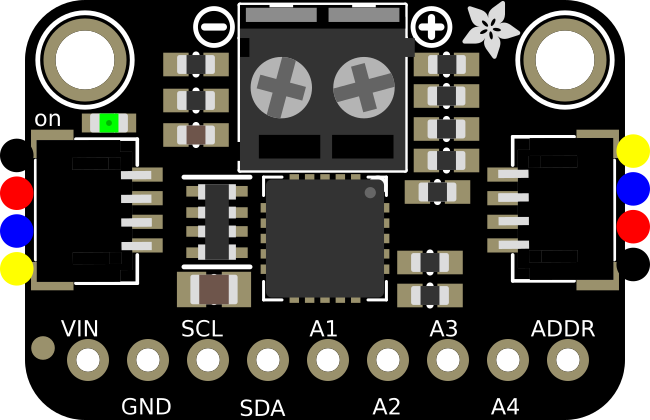
 Design with I2C Thermocouple Amplifier in Cirkit Designer
Introduction
The I2C Thermocouple Amplifier is a specialized device designed to amplify the small voltage generated by a thermocouple and convert it into a digital signal. This digital signal can then be read by microcontrollers or other devices using the I2C communication protocol. The amplifier ensures accurate and reliable temperature measurements, making it an essential component in applications requiring precise thermal monitoring.
Explore Projects Built with I2C Thermocouple Amplifier
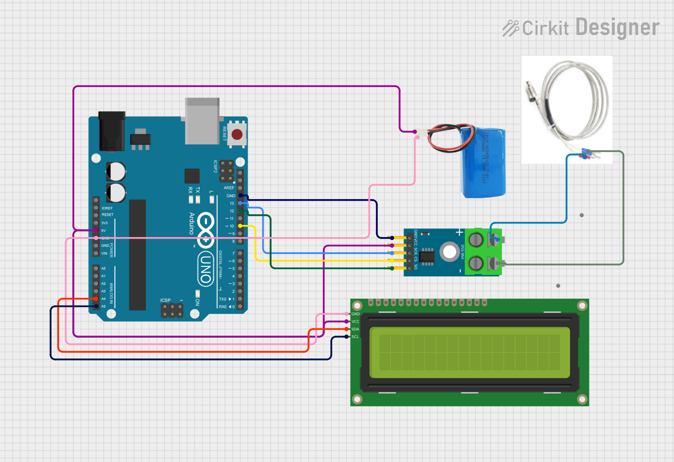 Open Project in Cirkit Designer
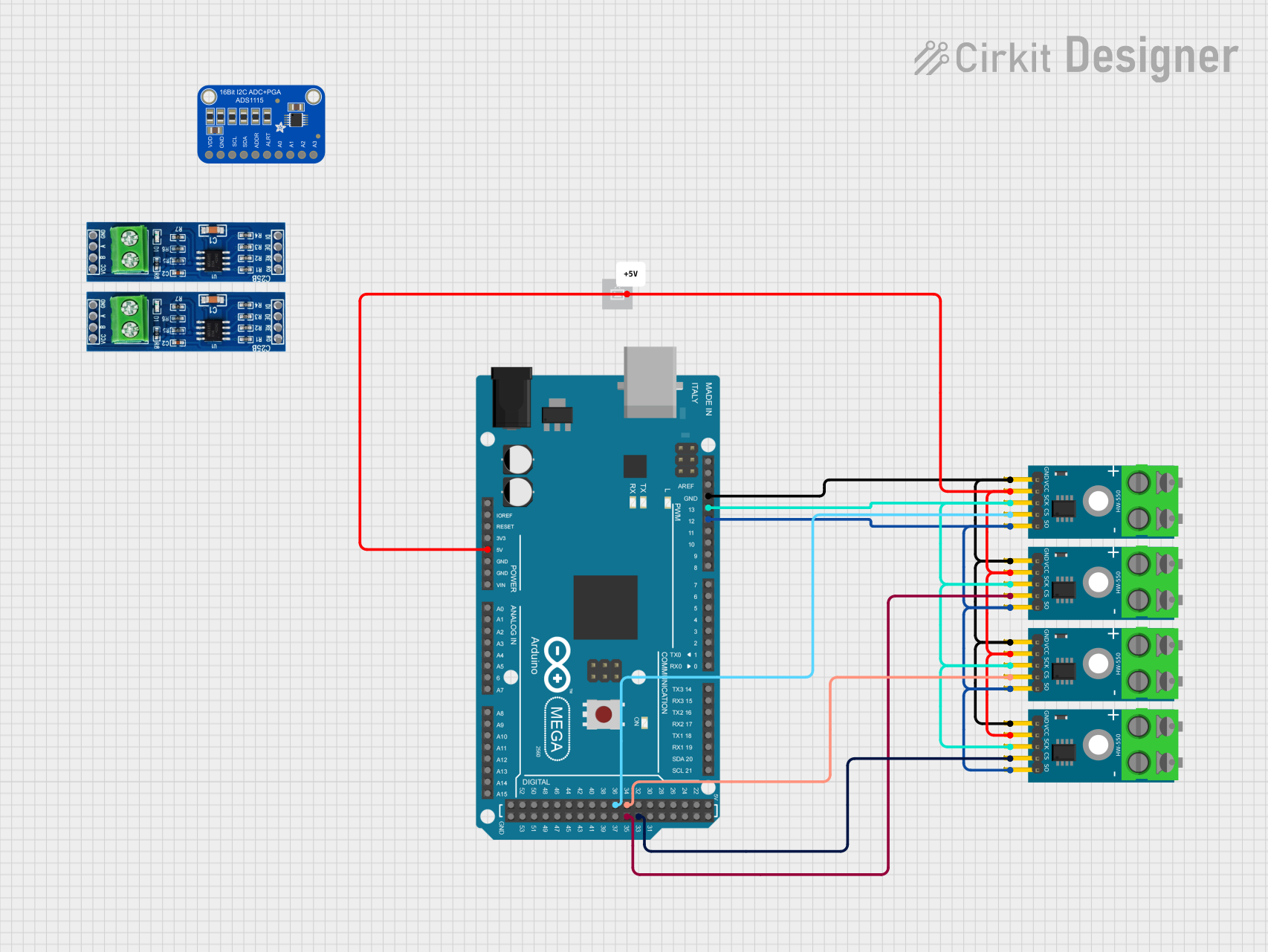 Open Project in Cirkit Designer
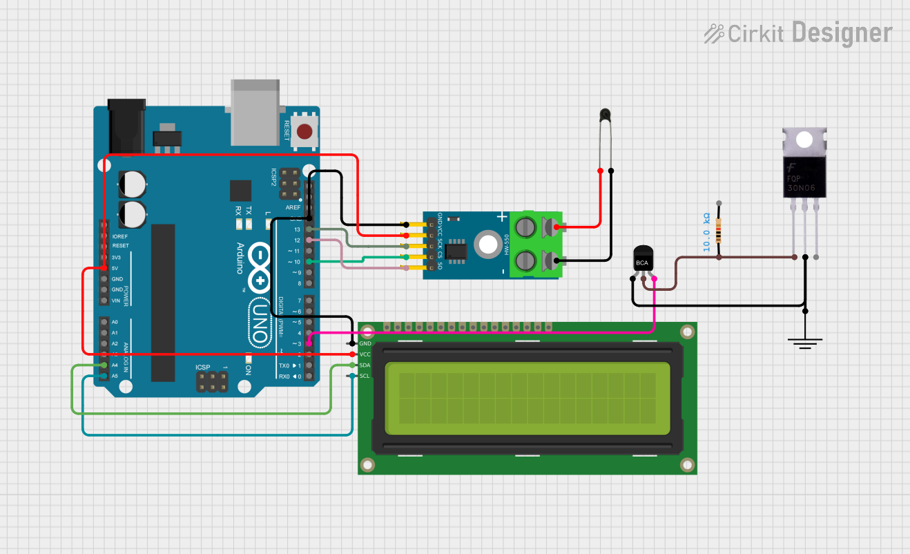 Open Project in Cirkit Designer
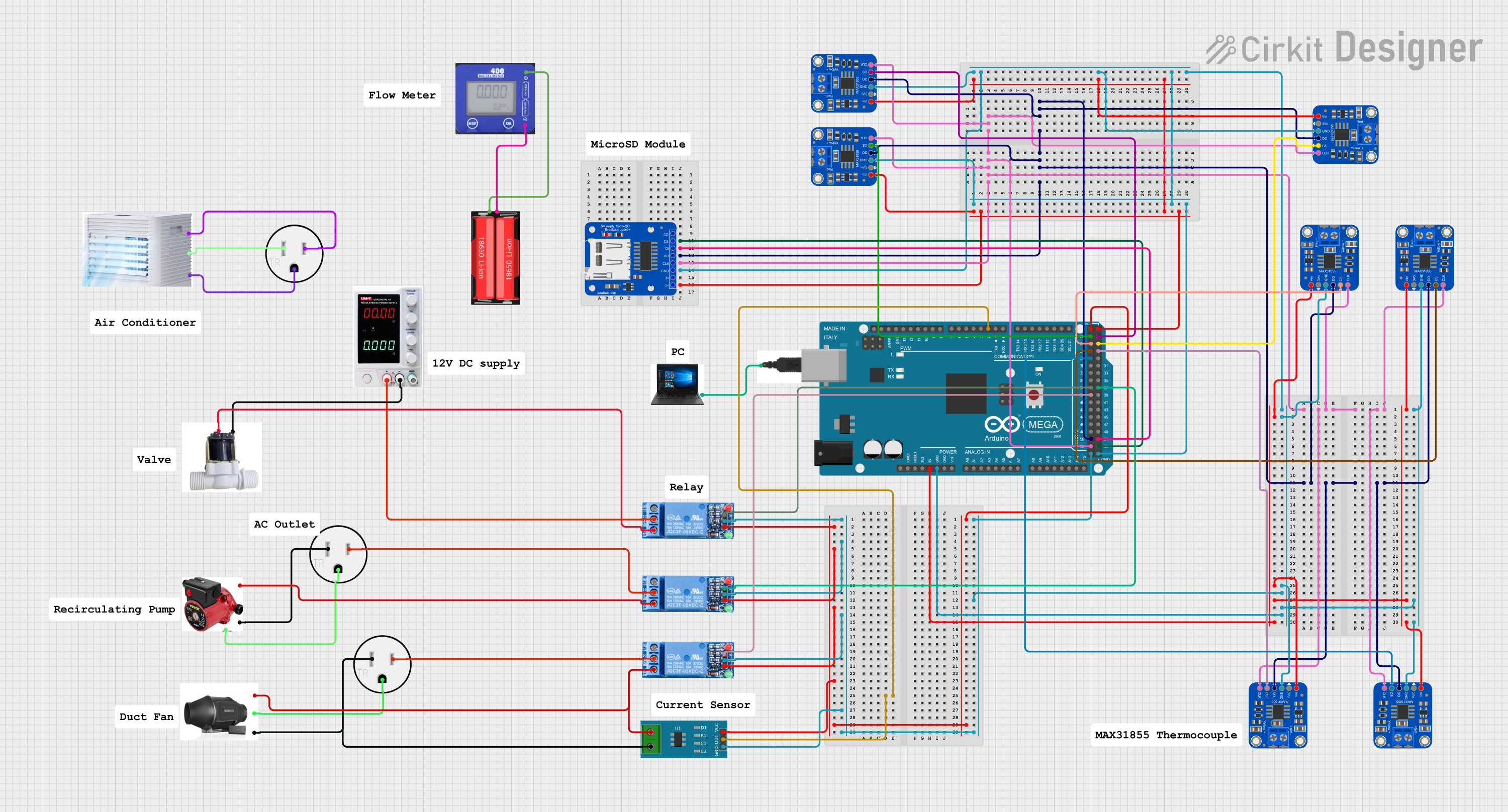 Open Project in Cirkit Designer
Explore Projects Built with I2C Thermocouple Amplifier
Open Project in Cirkit DesignerOpen Project in Cirkit DesignerOpen Project in Cirkit DesignerOpen Project in Cirkit DesignerCommon Applications and Use Cases
- Industrial temperature monitoring and control systems
- HVAC (Heating, Ventilation, and Air Conditioning) systems
- Scientific experiments requiring precise thermal measurements
- Food processing and storage temperature monitoring
- Embedded systems and IoT devices for environmental sensing
Technical Specifications
The following table outlines the key technical details of the I2C Thermocouple Amplifier:
| Parameter | Specification |
|---|---|
| Operating Voltage | 3.3V to 5V |
| Communication Protocol | I2C |
| Supported Thermocouple Types | K, J, T, N, S, E, B, R |
| Temperature Range | -200°C to +1350°C (depending on type) |
| Resolution | 0.25°C |
| Accuracy | ±2°C (typical, depending on type) |
| I2C Address | Configurable (default: 0x60) |
| Operating Current | ~1.5mA |
Pin Configuration and Descriptions
The I2C Thermocouple Amplifier typically has the following pinout:
| Pin | Name | Description |
|---|---|---|
| 1 | VIN | Power supply input (3.3V to 5V). |
| 2 | GND | Ground connection. |
| 3 | SCL | I2C clock line. Connect to the SCL pin of the microcontroller. |
| 4 | SDA | I2C data line. Connect to the SDA pin of the microcontroller. |
| 5 | T+ | Positive terminal for the thermocouple. |
| 6 | T- | Negative terminal for the thermocouple. |
| 7 | ADDR | Optional pin to configure the I2C address (pull high or low as needed). |
Usage Instructions
How to Use the Component in a Circuit
- Power the Amplifier: Connect the VIN pin to a 3.3V or 5V power source and the GND pin to ground.
- Connect the Thermocouple: Attach the positive (T+) and negative (T-) terminals of the thermocouple to the corresponding pins on the amplifier.
- I2C Communication: Connect the SCL and SDA pins to the corresponding I2C pins on your microcontroller (e.g., Arduino UNO).
- Pull-Up Resistors: Ensure that the I2C lines (SCL and SDA) have pull-up resistors (typically 4.7kΩ) if not already present on the board.
- Address Configuration: If using multiple amplifiers, configure their I2C addresses using the ADDR pin.
Important Considerations and Best Practices
- Ensure the thermocouple type matches the amplifier's supported types.
- Avoid long thermocouple wires to minimize noise and signal degradation.
- Use proper shielding for the thermocouple wires in noisy environments.
- Calibrate the amplifier if necessary for higher accuracy.
- Verify the I2C address of the amplifier before programming your microcontroller.
Example Code for Arduino UNO
Below is an example Arduino sketch to read temperature data from the I2C Thermocouple Amplifier:
#include <Wire.h> // Include the Wire library for I2C communication

#define I2C_ADDRESS 0x60 // Default I2C address of the amplifier

void setup() {
  Wire.begin(); // Initialize I2C communication
  Serial.begin(9600); // Start serial communication for debugging
  Serial.println("I2C Thermocouple Amplifier Test");
}

void loop() {
  Wire.beginTransmission(I2C_ADDRESS); // Start communication with the amplifier
  Wire.write(0x00); // Request temperature data (register 0x00)
  Wire.endTransmission();

  Wire.requestFrom(I2C_ADDRESS, 2); // Request 2 bytes of data
  if (Wire.available() == 2) {
    // Read the two bytes of temperature data
    uint8_t msb = Wire.read(); // Most significant byte
    uint8_t lsb = Wire.read(); // Least significant byte

    // Combine the bytes into a 16-bit value
    int16_t rawTemperature = (msb << 8) | lsb;

    // Convert the raw value to Celsius (example conversion, adjust as needed)
    float temperature = rawTemperature * 0.25;

    // Print the temperature to the Serial Monitor
    Serial.print("Temperature: ");
    Serial.print(temperature);
    Serial.println(" °C");
  } else {
    Serial.println("Error: No data received");
  }

  delay(1000); // Wait 1 second before the next reading
}
Troubleshooting and FAQs
Common Issues and Solutions
No Data Received
- Cause: Incorrect I2C address or wiring.
- Solution: Verify the I2C address and ensure proper connections for SCL and SDA.
Inaccurate Temperature Readings
- Cause: Incorrect thermocouple type or poor connections.
- Solution: Ensure the thermocouple type matches the amplifier's configuration and check the wiring.
Noise in Readings
- Cause: Long or unshielded thermocouple wires.
- Solution: Use shorter wires or shielded cables to reduce noise.
Amplifier Not Detected on I2C Bus
- Cause: Missing pull-up resistors or incorrect I2C wiring.
- Solution: Add 4.7kΩ pull-up resistors to the SCL and SDA lines if not already present.
FAQs
Q: Can I use this amplifier with a 3.3V microcontroller?
A: Yes, the amplifier is compatible with both 3.3V and 5V systems.
Q: What is the maximum distance for the thermocouple wires?
A: The maximum distance depends on the environment and wire type, but shorter wires are recommended to minimize noise.
Q: How do I change the I2C address?
A: Use the ADDR pin to configure the address. Refer to the datasheet for specific address settings.
Q: Can I use multiple amplifiers on the same I2C bus?
A: Yes, as long as each amplifier has a unique I2C address. Use the ADDR pin to configure different addresses.