How to Use 2-Channel Logic Level Shifter: Examples, Pinouts, and Specs
Introduction
The TXS0102 is a 2-channel bidirectional logic level shifter manufactured by Texas Instruments. It is designed to facilitate communication between devices operating at different voltage levels. This component is particularly useful in mixed-voltage systems, where one device operates at a lower voltage (e.g., 1.8V) and another at a higher voltage (e.g., 3.3V or 5V). The TXS0102 ensures seamless voltage translation without compromising signal integrity.
Explore Projects Built with 2-Channel Logic Level Shifter


Explore Projects Built with 2-Channel Logic Level Shifter
Common Applications and Use Cases
- Interfacing microcontrollers (e.g., Arduino, Raspberry Pi) with sensors or modules operating at different logic levels.
- Communication between 1.8V, 3.3V, and 5V devices in embedded systems.
- Voltage level translation in I²C, SPI, UART, and GPIO applications.
- Mixed-voltage environments in consumer electronics, industrial automation, and IoT devices.
Technical Specifications
The TXS0102 is a compact and efficient solution for voltage level shifting. Below are its key technical details:
Key Technical Details
- Voltage Range (VCCA): 1.2V to 3.6V
- Voltage Range (VCCB): 1.65V to 5.5V
- Data Rate: Up to 24 Mbps (push-pull) or 2 Mbps (open-drain)
- Channels: 2 bidirectional channels
- Operating Temperature Range: -40°C to +85°C
- Package Options: Available in small packages such as DCT (SOT-23-8) and DCU (VSSOP-8)
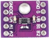
Pin Configuration and Descriptions
The TXS0102 comes in an 8-pin package. Below is the pinout and description:
| Pin | Name | Type | Description |
|---|---|---|---|
| 1 | VCCA | Power | Supply voltage for the A-side logic (1.2V to 3.6V). |
| 2 | A1 | Input/Output | Channel 1 data line for the A-side logic. |
| 3 | A2 | Input/Output | Channel 2 data line for the A-side logic. |
| 4 | GND | Ground | Ground connection for the device. |
| 5 | B2 | Input/Output | Channel 2 data line for the B-side logic. |
| 6 | B1 | Input/Output | Channel 1 data line for the B-side logic. |
| 7 | OE | Input | Output enable pin. Active HIGH. Pull LOW to disable the device. |
| 8 | VCCB | Power | Supply voltage for the B-side logic (1.65V to 5.5V). |
Usage Instructions
The TXS0102 is straightforward to use in circuits. Below are the steps and considerations for proper usage:
How to Use the TXS0102 in a Circuit
Power Connections:
- Connect the lower voltage supply (e.g., 1.8V or 3.3V) to the VCCA pin.
- Connect the higher voltage supply (e.g., 3.3V or 5V) to the VCCB pin.
- Ensure a common ground connection between the TXS0102 and all devices in the circuit.
Data Lines:
- Connect the lower voltage logic signals to the A1 and A2 pins.
- Connect the higher voltage logic signals to the B1 and B2 pins.
- The TXS0102 automatically detects the direction of data flow, so no additional control is required.
Output Enable (OE):
- Pull the OE pin HIGH to enable the device.
- Pull the OE pin LOW to disable the device and place all I/O pins in a high-impedance state.
Pull-Up Resistors:
- For open-drain communication protocols like I²C, use external pull-up resistors on both the A and B sides.
- Choose resistor values based on the operating voltage and desired data rate.
Example: Connecting TXS0102 to an Arduino UNO
Below is an example of using the TXS0102 to interface an Arduino UNO (5V logic) with a 3.3V sensor:
Circuit Connections
- VCCA: Connect to the 3.3V supply.
- VCCB: Connect to the 5V supply from the Arduino.
- GND: Connect to the common ground.
- A1/A2: Connect to the 3.3V sensor's data lines.
- B1/B2: Connect to the Arduino's data lines.
- OE: Connect to 5V (HIGH) to enable the device.
Arduino Code Example
// Example: Reading data from a 3.3V sensor using TXS0102 with Arduino UNO

#include <Wire.h> // Include Wire library for I²C communication

void setup() {
  Wire.begin(); // Initialize I²C communication
  Serial.begin(9600); // Start serial communication for debugging
  Serial.println("TXS0102 Level Shifter Example");
}

void loop() {
  Wire.beginTransmission(0x40); // Address of the 3.3V sensor
  Wire.write(0x00); // Command to read data (example command)
  Wire.endTransmission();

  Wire.requestFrom(0x40, 2); // Request 2 bytes of data from the sensor
  if (Wire.available() == 2) {
    int data = Wire.read() << 8 | Wire.read(); // Combine two bytes into one value
    Serial.print("Sensor Data: ");
    Serial.println(data);
  }

  delay(1000); // Wait 1 second before the next read
}
Important Considerations and Best Practices
- Ensure that the VCCA voltage is always less than or equal to the VCCB voltage.
- Avoid leaving the OE pin floating; always connect it to a defined logic level.
- For high-speed signals, minimize trace lengths to reduce signal degradation.
- Use decoupling capacitors (e.g., 0.1 µF) near the VCCA and VCCB pins to stabilize the power supply.
Troubleshooting and FAQs
Common Issues and Solutions
No Signal Translation:
- Ensure the OE pin is pulled HIGH to enable the device.
- Verify that the power supply voltages are within the specified ranges.
Signal Distortion or Noise:
- Check for proper grounding and minimize trace lengths.
- Add decoupling capacitors near the power supply pins.
I²C Communication Fails:
- Ensure pull-up resistors are present on both the A and B sides.
- Verify the I²C address and connections.
Device Overheating:
- Confirm that the supply voltages do not exceed the maximum ratings.
- Check for short circuits or excessive current draw.
FAQs
Q1: Can the TXS0102 handle SPI communication?
A1: Yes, the TXS0102 supports SPI communication as long as the data rate does not exceed 24 Mbps.
Q2: Do I need external pull-up resistors for GPIO signals?
A2: No, pull-up resistors are not required for push-pull signals. However, they are necessary for open-drain protocols like I²C.
Q3: Can I use the TXS0102 for 5V to 1.8V level shifting?
A3: Yes, the TXS0102 supports level shifting between 5V and 1.8V as long as the supply voltages are correctly configured.
Q4: What happens if I leave the OE pin floating?
A4: Leaving the OE pin floating may cause unpredictable behavior. Always connect it to a defined logic level (HIGH or LOW).