Cirkit Designer Logo
Cirkit Designer
Your all-in-one circuit design IDE
Home / 
Component Documentation

How to Use SparkFun RedBoard Artemis ATP: Examples, Pinouts, and Specs

Image of SparkFun RedBoard Artemis ATP
Cirkit Designer LogoDesign with SparkFun RedBoard Artemis ATP in Cirkit Designer

Introduction

The SparkFun RedBoard Artemis ATP is an advanced Arduino-compatible development board that harnesses the power of the Artemis module. It is designed to be a flexible and powerful platform for both prototyping and production use. With integrated Bluetooth Low Energy (BLE) and USB-C connectivity, the RedBoard Artemis ATP is ideal for projects requiring wireless communication and robust processing capabilities. Common applications include wearable devices, sensor networks, and IoT (Internet of Things) projects.

Explore Projects Built with SparkFun RedBoard Artemis ATP

Use Cirkit Designer to design, explore, and prototype these projects online. Some projects support real-time simulation. Click "Open Project" to start designing instantly!
SparkFun RedBoard Controlled Multi-Servo Circuit
Image of Sassy-Display: A project utilizing SparkFun RedBoard Artemis ATP in a practical application
This circuit consists of a SparkFun RedBoard, which is an Arduino-compatible development platform, connected to four servo motors. The RedBoard provides 5V power and ground to each servo, and it also controls the servos using PWM signals on pins D3, D4, D5, and D6. The purpose of this circuit is to independently control the position or speed of four servos, commonly used in robotics and RC applications.
Cirkit Designer LogoOpen Project in Cirkit Designer
Location-Aware IoT Device with GSM Communication and LED Indicators
Image of LEDBikeVest-CircuitDiagram: A project utilizing SparkFun RedBoard Artemis ATP in a practical application
This circuit features an Arduino Nano for GSM communication and GPS tracking, and a Wemos D1 Mini for controlling WS2812 RGB LED strips. It includes motion sensing with an MPU-6050 and is powered by Li-ion batteries with TP4056 charging modules. The microcontrollers' code is not yet implemented.
Cirkit Designer LogoOpen Project in Cirkit Designer
Battery-Powered Arduino UNO Smart Light with NeoPixel and ADXL345
Image of Cubagick: A project utilizing SparkFun RedBoard Artemis ATP in a practical application
This circuit is a battery-powered system featuring an Arduino UNO that controls an Adafruit NeoPixel Stick and interfaces with an ADXL345 accelerometer and an ILI9341 TFT display. The TP4056 module charges a 18650 battery, which powers the system through a DC-DC converter. The Arduino code drives the NeoPixel Stick to display a red light sequence.
Cirkit Designer LogoOpen Project in Cirkit Designer
Arduino Nano Based GPS Tracker with GSM Module and Panic Buttons
Image of gps tracking system : A project utilizing SparkFun RedBoard Artemis ATP in a practical application
This circuit features an Arduino Nano interfaced with a GPS NEO 6M module for location tracking and a SIM800L GSM module for cellular communication. The Arduino is programmed to send an SMS with GPS coordinates when a yellow arcade button is pressed, and it can also initiate a call. The circuit is powered by a Polymer Lithium Ion Battery, and pull-up resistors are connected to the arcade buttons to ensure stable input signals to the Arduino.
Cirkit Designer LogoOpen Project in Cirkit Designer

Explore Projects Built with SparkFun RedBoard Artemis ATP

Use Cirkit Designer to design, explore, and prototype these projects online. Some projects support real-time simulation. Click "Open Project" to start designing instantly!
Image of Sassy-Display: A project utilizing SparkFun RedBoard Artemis ATP in a practical application
SparkFun RedBoard Controlled Multi-Servo Circuit
This circuit consists of a SparkFun RedBoard, which is an Arduino-compatible development platform, connected to four servo motors. The RedBoard provides 5V power and ground to each servo, and it also controls the servos using PWM signals on pins D3, D4, D5, and D6. The purpose of this circuit is to independently control the position or speed of four servos, commonly used in robotics and RC applications.
Cirkit Designer LogoOpen Project in Cirkit Designer
Image of LEDBikeVest-CircuitDiagram: A project utilizing SparkFun RedBoard Artemis ATP in a practical application
Location-Aware IoT Device with GSM Communication and LED Indicators
This circuit features an Arduino Nano for GSM communication and GPS tracking, and a Wemos D1 Mini for controlling WS2812 RGB LED strips. It includes motion sensing with an MPU-6050 and is powered by Li-ion batteries with TP4056 charging modules. The microcontrollers' code is not yet implemented.
Cirkit Designer LogoOpen Project in Cirkit Designer
Image of Cubagick: A project utilizing SparkFun RedBoard Artemis ATP in a practical application
Battery-Powered Arduino UNO Smart Light with NeoPixel and ADXL345
This circuit is a battery-powered system featuring an Arduino UNO that controls an Adafruit NeoPixel Stick and interfaces with an ADXL345 accelerometer and an ILI9341 TFT display. The TP4056 module charges a 18650 battery, which powers the system through a DC-DC converter. The Arduino code drives the NeoPixel Stick to display a red light sequence.
Cirkit Designer LogoOpen Project in Cirkit Designer
Image of gps tracking system : A project utilizing SparkFun RedBoard Artemis ATP in a practical application
Arduino Nano Based GPS Tracker with GSM Module and Panic Buttons
This circuit features an Arduino Nano interfaced with a GPS NEO 6M module for location tracking and a SIM800L GSM module for cellular communication. The Arduino is programmed to send an SMS with GPS coordinates when a yellow arcade button is pressed, and it can also initiate a call. The circuit is powered by a Polymer Lithium Ion Battery, and pull-up resistors are connected to the arcade buttons to ensure stable input signals to the Arduino.
Cirkit Designer LogoOpen Project in Cirkit Designer

Technical Specifications

Key Technical Details

  • Microcontroller: Ambiq Apollo3 ARM Cortex-M4F
  • Operating Voltage: 3.3V
  • Input Voltage (recommended): 5V via USB-C or 4-6V via the VIN pin
  • Digital I/O Pins: 48, all interrupt capable
  • PWM Channels: All digital pins
  • Analog Input Channels: 10 (ADC resolution of 14 bits)
  • Analog Outputs: 2 (DAC resolution of 10 bits)
  • UARTs: 2
  • I2C Buses: 2
  • SPI Buses: 2
  • Qwiic Connector: Yes
  • Flash Memory: 1MB
  • SRAM: 384KB
  • Clock Speed: 48MHz
  • BLE: Bluetooth 5.0 (with FCC Certification)
  • USB: 1x USB-C for programming and power

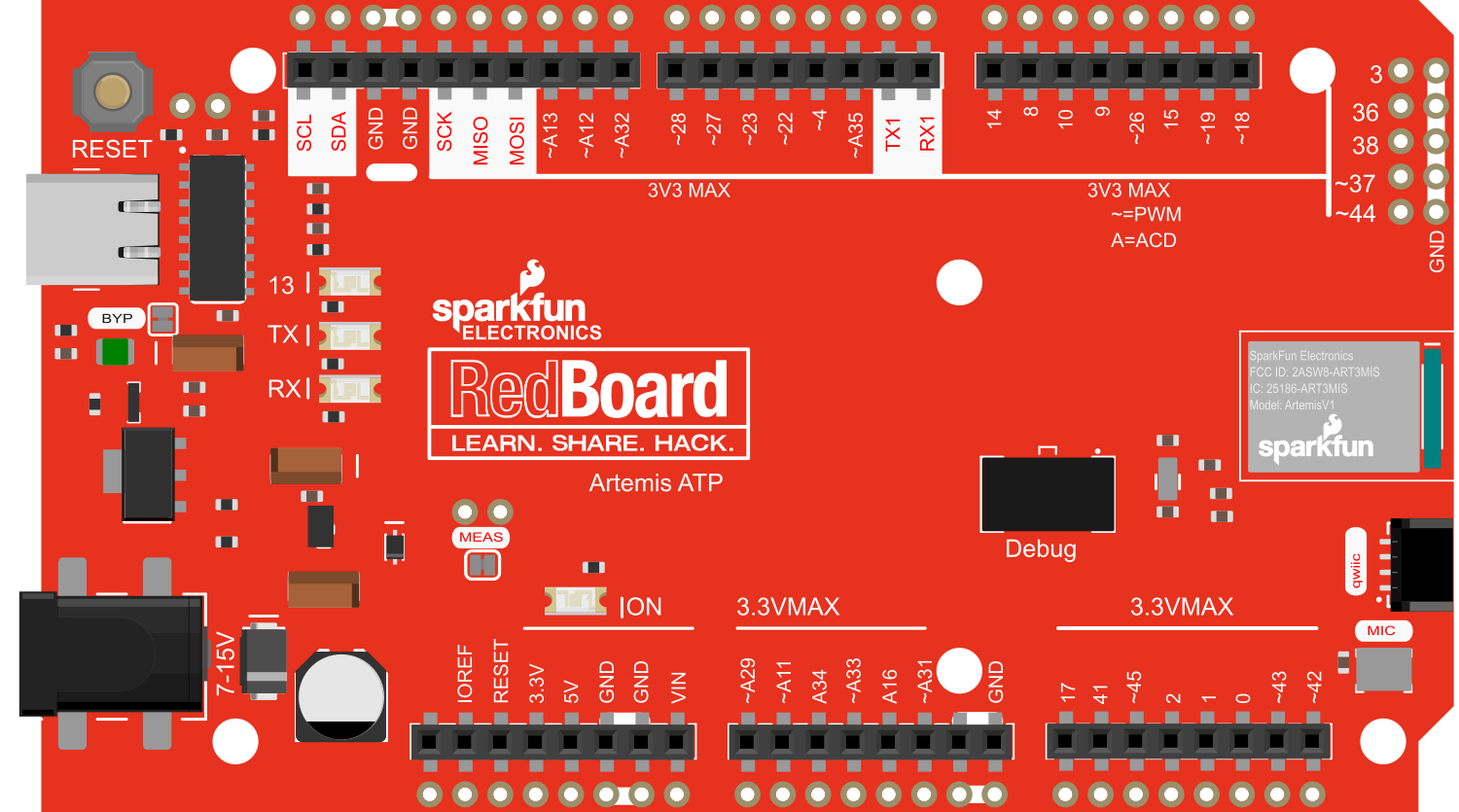
Pin Configuration and Descriptions

Pin Number Function Description
1-48 Digital I/O All pins can be used as digital input/output
A0-A9 Analog Input Analog to Digital Converter (ADC) channels
DAC0, DAC1 Analog Output Digital to Analog Converter (DAC) channels
RX1, TX1 UART 1 Serial communication
RX2, TX2 UART 2 Secondary serial communication
SDA1, SCL1 I2C Bus 1 Inter-Integrated Circuit communication
SDA2, SCL2 I2C Bus 2 Secondary I2C bus for additional peripherals
SCK, MISO, MOSI SPI Bus Serial Peripheral Interface communication
GND Ground Common ground
VIN Voltage Input Unregulated input voltage for the board
3V3 3.3V Output Regulated 3.3V power output
RST Reset Active-low reset input
PWR LED Power Indicator LED that lights up when the board is powered
CHG LED Charge Indicator LED that indicates battery charging status

Usage Instructions

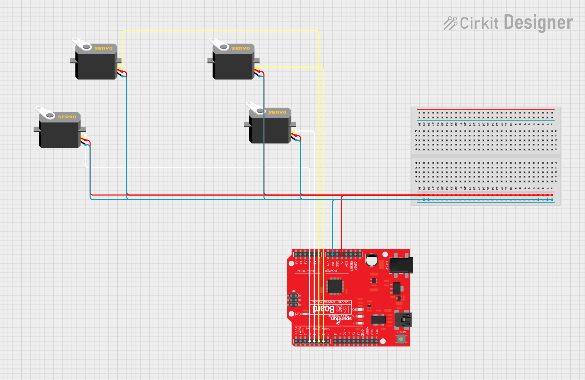
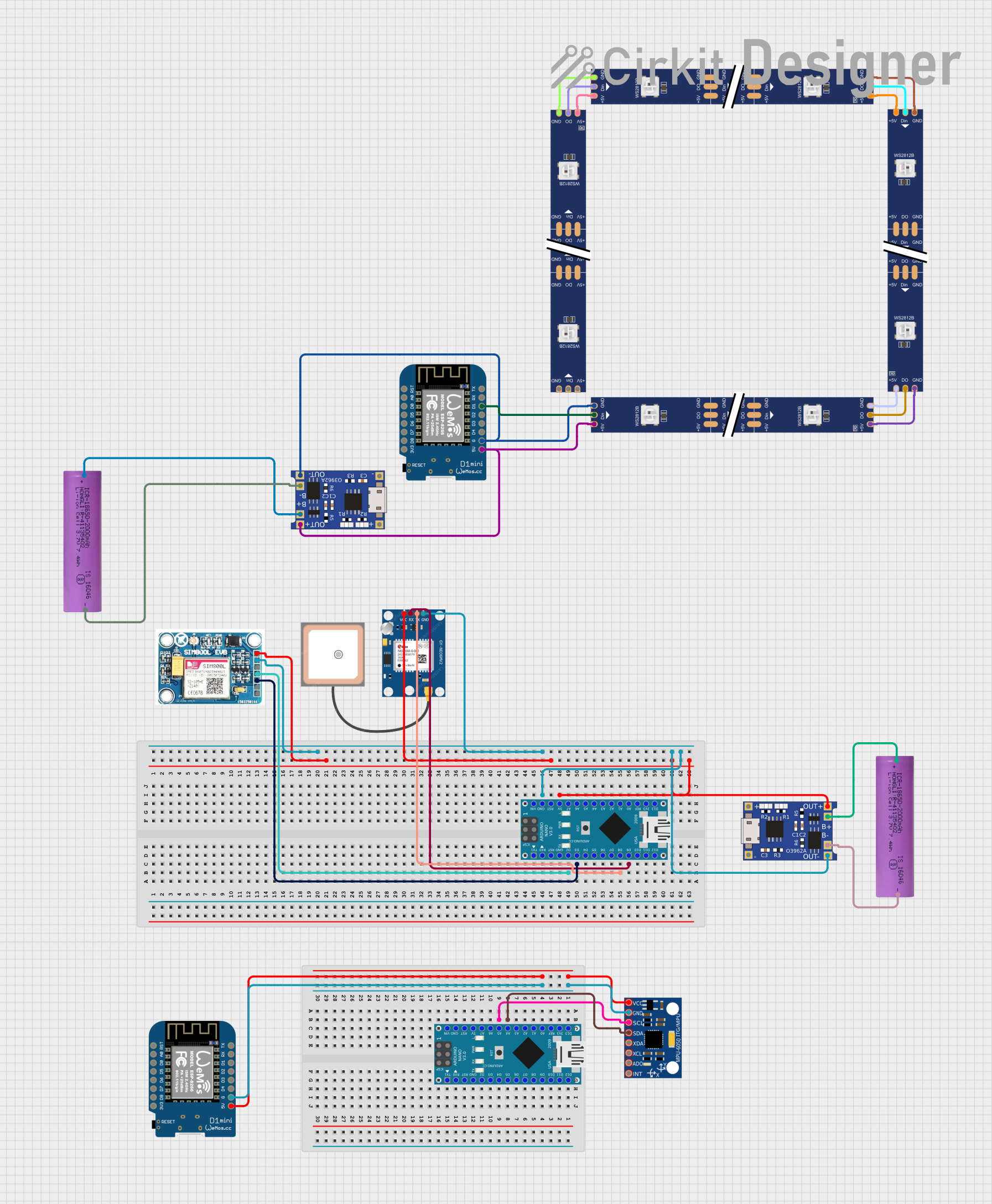
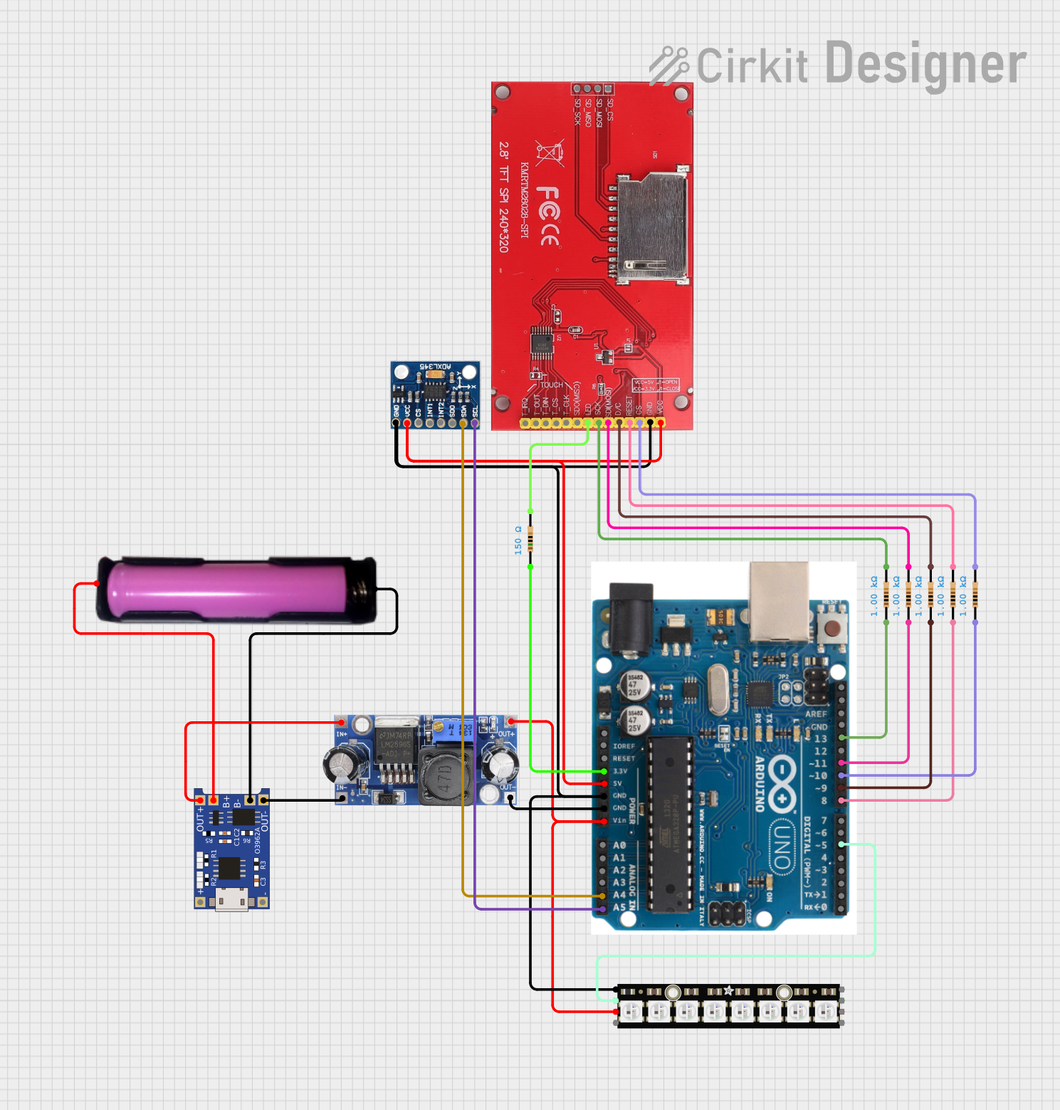
Integrating with a Circuit

To use the SparkFun RedBoard Artemis ATP in a circuit:

  1. Connect the board to your computer using a USB-C cable.
  2. Ensure that the board is recognized by your computer and the appropriate drivers are installed.
  3. Use the Arduino IDE or other compatible software to write and upload your code.
  4. Connect external components to the I/O pins as required for your project, taking care to match the voltage levels and current capabilities.

Best Practices

  • Always ensure that the power supply voltage does not exceed the recommended input voltage range.
  • When connecting external components, consider the current draw and ensure it is within the limits of the board's power regulator.
  • Use the onboard Qwiic connector for easy I2C communication with compatible devices without soldering.
  • Utilize the board's BLE capabilities for wireless communication in your projects.

Example Code for Arduino UNO

Here is a simple example of how to blink an LED on pin 13 of the SparkFun RedBoard Artemis ATP using the Arduino IDE:

// Define the LED pin
const int ledPin = 13;

// The setup function runs once when you press reset or power the board
void setup() {
  // Initialize the digital pin as an output.
  pinMode(ledPin, OUTPUT);
}

// The loop function runs over and over again forever
void loop() {
  digitalWrite(ledPin, HIGH);   // Turn the LED on (HIGH is the voltage level)
  delay(1000);                  // Wait for a second
  digitalWrite(ledPin, LOW);    // Turn the LED off by making the voltage LOW
  delay(1000);                  // Wait for a second
}

Troubleshooting and FAQs

Common Issues

  • Board not recognized: Ensure that the USB-C cable is properly connected and that the drivers are installed.
  • Failure to upload code: Check the selected board and port in the Arduino IDE. Ensure that the correct drivers are installed.
  • Unexpected behavior in circuits: Verify that all connections are correct and that components are functioning as expected.

Solutions and Tips

  • If the board is not recognized, try a different USB port or cable and restart the Arduino IDE.
  • For upload issues, double-check the board selection and COM port. Also, ensure that the bootloader is not corrupted.
  • Use a multimeter to check for proper voltage levels and continuity in your circuit.

FAQs

Q: Can I power the RedBoard Artemis ATP with a battery? A: Yes, you can power the board with a battery connected to the VIN pin.

Q: Is the RedBoard Artemis ATP compatible with all Arduino shields? A: While it is Arduino-compatible, not all shields may be compatible due to differences in pin layout and voltage levels. Check the shield specifications and the Artemis ATP pinout to ensure compatibility.

Q: How do I use the BLE functionality? A: BLE functionality can be accessed using the appropriate libraries in the Arduino IDE. Refer to the SparkFun Artemis BLE guide for detailed instructions.

For further assistance, consult the SparkFun forums or contact technical support.