How to Use ARDUINO UNO: Examples, Pinouts, and Specs
Introduction
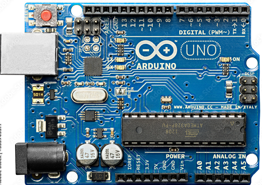
The Arduino Uno, manufactured by ZEEL with the part ID UNO, is a widely recognized and utilized microcontroller board. It is built around the ATmega328P microcontroller and is designed for ease of use and flexibility, making it a staple in the world of electronics for hobbyists, educators, and professionals alike. The Uno is particularly favored for prototyping and DIY electronics projects due to its open-source platform and extensive community support.
Explore Projects Built with ARDUINO UNO
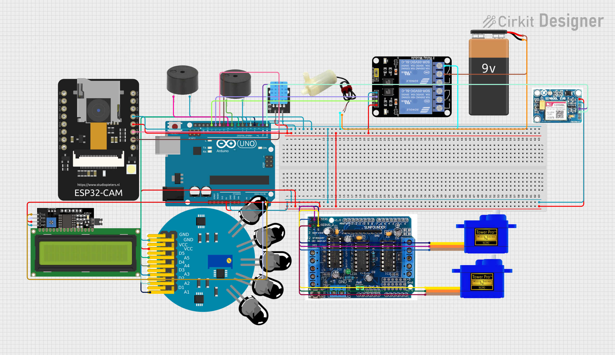
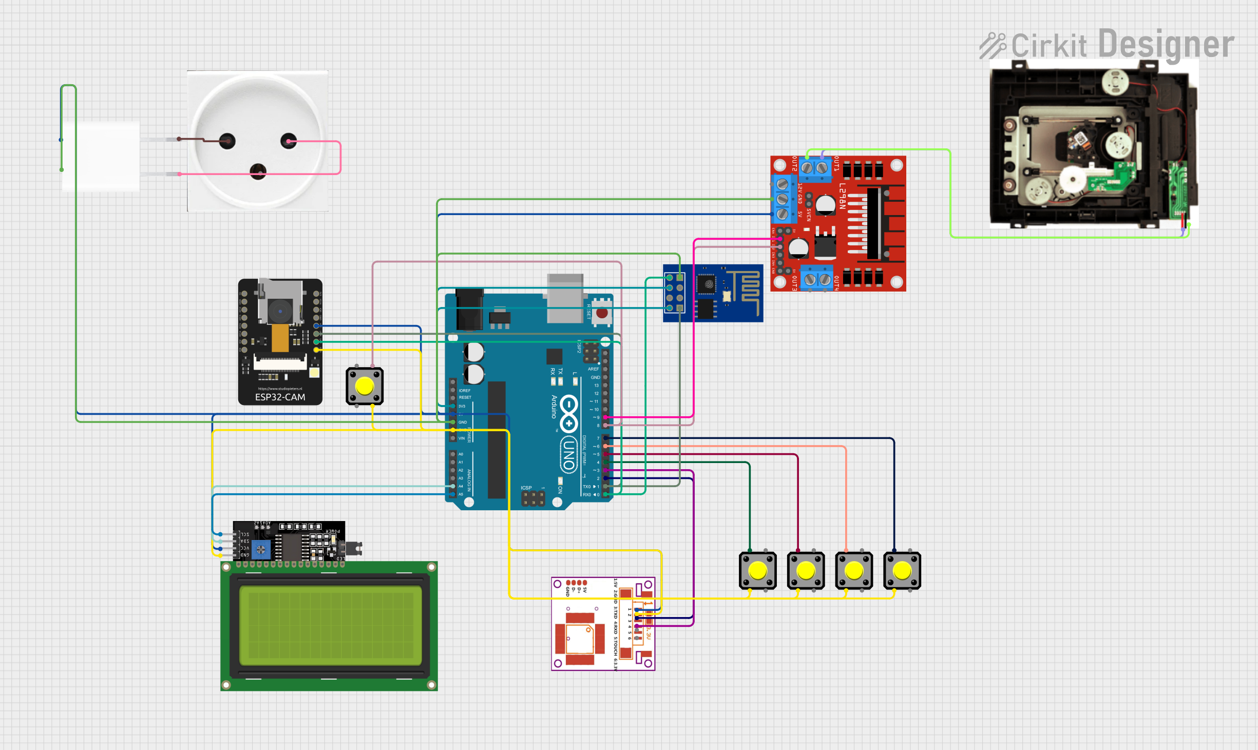
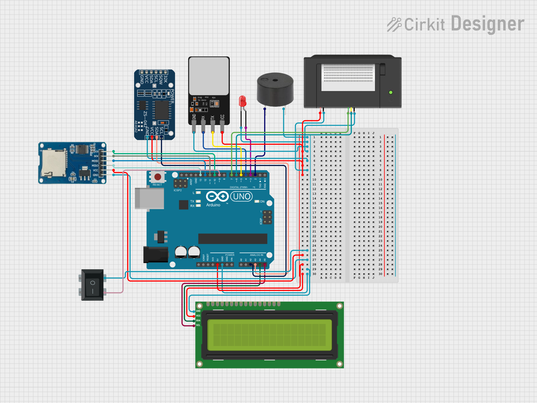
Explore Projects Built with ARDUINO UNO
Common Applications and Use Cases
- Educational projects and learning the basics of electronics and programming
- Prototyping for inventions and product development
- DIY home automation systems
- Robotics and control systems
- Sensor data collection and environmental monitoring
- Interactive artwork and installations
Technical Specifications
Key Technical Details
- Microcontroller: ATmega328P
- Operating Voltage: 5V
- Input Voltage (recommended): 7-12V
- Input Voltage (limit): 6-20V
- Digital I/O Pins: 14 (of which 6 provide PWM output)
- Analog Input Pins: 6
- DC Current per I/O Pin: 20 mA
- DC Current for 3.3V Pin: 50 mA
- Flash Memory: 32 KB (ATmega328P) of which 0.5 KB used by bootloader
- SRAM: 2 KB (ATmega328P)
- EEPROM: 1 KB (ATmega328P)
- Clock Speed: 16 MHz
- LED_BUILTIN: Pin 13
Pin Configuration and Descriptions
| Pin Number | Function | Description |
|---|---|---|
| 1-13 | Digital I/O | Digital input/output pins (0-13), PWM on 3,5,6,9,10,11 |
| 14-19 | Analog Input | Analog input pins (A0-A5) |
| 20 | RESET | Used to reset the microcontroller |
| 21-22 | I2C | SDA (data line) and SCL (clock line) for I2C communication |
| 23-24 | TX/RX | Serial communication (TX1, RX1) |
| 25 | 3V3 | 3.3V power supply pin |
| 26 | 5V | 5V power supply pin |
| 27 | GND | Ground pin |
| 28 | GND | Ground pin |
| 29 | Vin | Input voltage to Arduino when using an external power source |
Usage Instructions
How to Use the Arduino Uno in a Circuit
Powering the Board:
- Connect the Arduino Uno to a computer via a USB cable or supply power through the DC power jack or Vin pin.
- Ensure that the power supply is within the recommended voltage range (7-12V).
Connecting Components:
- Use the digital and analog pins to connect sensors, actuators, displays, and other components.
- Remember to connect a ground wire from the Arduino to the ground of your circuit.
Programming the Board:
- Use the Arduino IDE to write and upload sketches (programs) to the board.
- Select the correct board and port in the IDE before uploading.
Important Considerations and Best Practices
- Always disconnect the Arduino from power sources before making or altering connections.
- Do not exceed the maximum current ratings for the I/O pins to prevent damage.
- Use external power supplies when connecting components that require more current than the Arduino can provide.
- Avoid exposing the board to extreme temperatures, moisture, or dust.
Troubleshooting and FAQs
Common Issues
- Arduino not recognized by computer:
- Check the USB cable and port.
- Ensure the correct drivers are installed.
- Sketch not uploading:
- Verify the correct board and port are selected in the Arduino IDE.
- Check for errors in the code and ensure the correct bootloader is used.
- Unexpected behavior in circuits:
- Double-check wiring and connections.
- Ensure power supply is stable and within the recommended range.
Solutions and Tips for Troubleshooting
- Reset the Arduino Uno by pressing the onboard reset button.
- Use the Arduino IDE's Serial Monitor to debug and print out messages from the Arduino.
- Consult the extensive online community forums for advice and solutions.
Example Code for Arduino Uno
Here is a simple example of blinking the onboard LED connected to pin 13:
// Define the LED pin
const int ledPin = 13;

// The setup function runs once when you press reset or power the board
void setup() {
  // Initialize the digital pin as an output.
  pinMode(ledPin, OUTPUT);
}

// The loop function runs over and over again forever
void loop() {
  digitalWrite(ledPin, HIGH);   // Turn the LED on
  delay(1000);                  // Wait for a second
  digitalWrite(ledPin, LOW);    // Turn the LED off
  delay(1000);                  // Wait for a second
}
Remember to wrap your code comments to limit line length to 80 characters, as shown above. This ensures readability and maintains a clean, professional appearance in your code documentation.