
How to Use External +24V Supply : Examples, Pinouts, and Specs
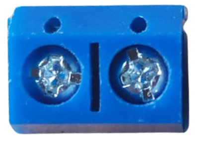
 Design with External +24V Supply in Cirkit Designer
Introduction
The External +24V Supply is a power supply unit designed to provide a stable +24 volts DC output. It is commonly used to power a wide range of electronic devices, industrial equipment, and circuits that require a reliable and consistent voltage source. This component is essential in applications such as motor drivers, industrial automation systems, LED lighting, and other devices that operate at 24V DC.
Explore Projects Built with External +24V Supply
 Open Project in Cirkit Designer
 Open Project in Cirkit Designer
 Open Project in Cirkit Designer
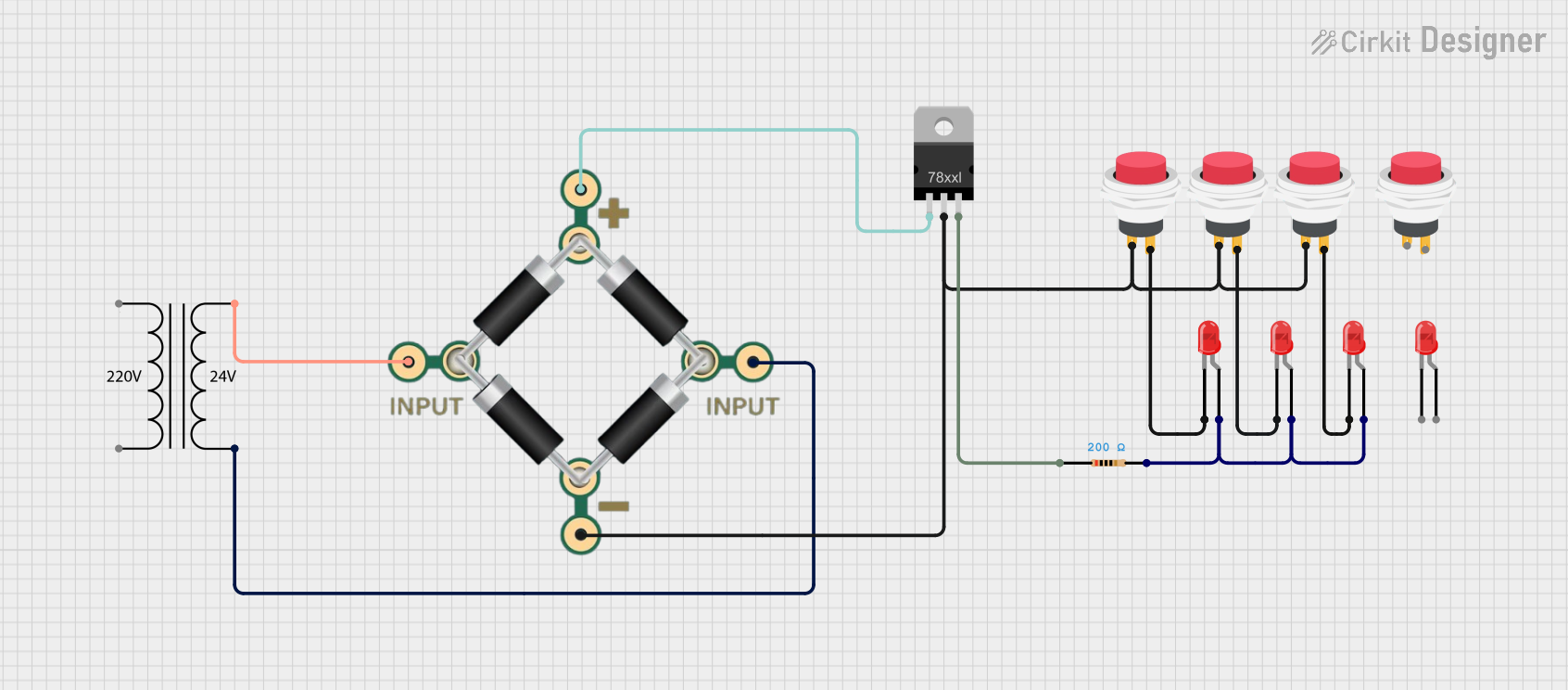 Open Project in Cirkit Designer
Explore Projects Built with External +24V Supply
Open Project in Cirkit DesignerOpen Project in Cirkit DesignerOpen Project in Cirkit DesignerOpen Project in Cirkit DesignerTechnical Specifications
Below are the key technical details of the External +24V Supply:
| Parameter | Specification |
|---|---|
| Output Voltage | +24V DC |
| Input Voltage Range | 100-240V AC (typical for most models) |
| Output Current | Varies by model (e.g., 1A, 2A, 5A) |
| Power Rating | Depends on current (e.g., 24W, 48W) |
| Ripple and Noise | < 1% of output voltage |
| Efficiency | Typically 85-95% |
| Operating Temperature | -10°C to +50°C |
| Protection Features | Overvoltage, Overcurrent, Short Circuit |
Pin Configuration and Descriptions
The External +24V Supply typically has the following connections:
| Pin/Terminal | Description |
|---|---|
| L (Line) | AC live input (connect to mains power) |
| N (Neutral) | AC neutral input (connect to mains power) |
| GND (Ground) | Earth ground for safety |
| +24V | Positive DC output terminal |
| GND | Negative DC output terminal (common ground) |
Usage Instructions
How to Use the External +24V Supply in a Circuit
Connect the AC Input:
- Ensure the power supply is rated for your local mains voltage (e.g., 110V or 220V AC).
- Connect the "L" terminal to the live wire and the "N" terminal to the neutral wire.
- Optionally, connect the "GND" terminal to earth ground for safety.
Connect the DC Output:
- Connect the "+24V" terminal to the positive input of your circuit or device.
- Connect the "GND" terminal to the ground or negative input of your circuit.
Power On:
- After verifying all connections, plug the power supply into the mains outlet and switch it on.
- Use a multimeter to confirm the output voltage is +24V DC before connecting sensitive devices.
Important Considerations and Best Practices
- Load Capacity: Ensure the total current draw of your circuit does not exceed the rated output current of the power supply.
- Ventilation: Place the power supply in a well-ventilated area to prevent overheating.
- Polarity: Double-check the polarity of the DC output connections to avoid damaging your circuit.
- Safety: Always disconnect the power supply from the mains before making or modifying connections.
Example: Using with an Arduino UNO
The External +24V Supply can be used to power devices connected to an Arduino UNO. However, since the Arduino operates at 5V, a step-down voltage regulator (e.g., LM2596) is required to convert 24V to 5V.
Circuit Diagram
- Connect the +24V output to the input of the step-down regulator.
- Set the regulator output to 5V using its adjustment screw.
- Connect the regulator's 5V output to the Arduino's 5V pin and GND to GND.
Sample Code
// Example code to blink an LED connected to pin 13 of Arduino UNO
// Ensure the Arduino is powered via the step-down regulator (5V output)

void setup() {
  pinMode(13, OUTPUT); // Set pin 13 as an output
}

void loop() {
  digitalWrite(13, HIGH); // Turn the LED on
  delay(1000);            // Wait for 1 second
  digitalWrite(13, LOW);  // Turn the LED off
  delay(1000);            // Wait for 1 second
}
Troubleshooting and FAQs
Common Issues
No Output Voltage:
- Cause: AC input is not connected or the power supply is switched off.
- Solution: Verify the AC input connections and ensure the power supply is turned on.
Overheating:
- Cause: Insufficient ventilation or excessive load.
- Solution: Reduce the load or improve airflow around the power supply.
Device Not Powering On:
- Cause: Incorrect polarity or loose connections.
- Solution: Double-check the polarity and ensure all connections are secure.
Voltage Fluctuations:
- Cause: Overloading or a faulty power supply.
- Solution: Reduce the load or replace the power supply if necessary.
FAQs
Q: Can I use this power supply to charge batteries?
A: No, this power supply is not designed for battery charging. Use a dedicated battery charger.Q: Is the power supply waterproof?
A: Most models are not waterproof. Use them in dry environments or enclosures.Q: Can I connect multiple devices to the same power supply?
A: Yes, as long as the total current draw does not exceed the power supply's rated output current.
By following these guidelines, you can safely and effectively use the External +24V Supply in your projects.