How to Use Grove - 4-Channel SPDT Relay: Examples, Pinouts, and Specs
Introduction
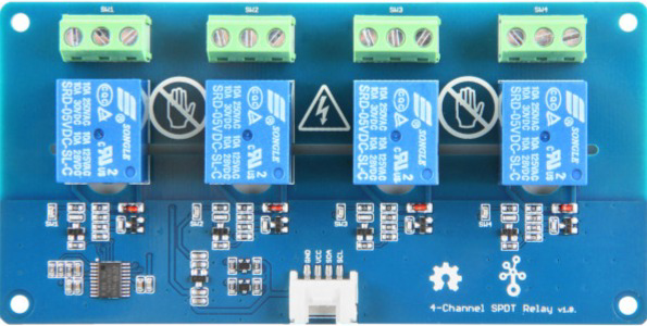
The Grove - 4-Channel SPDT Relay (Manufacturer Part ID: 103020133) by Seeed Studio is a versatile relay module designed to control multiple devices using a single microcontroller output. It features four Single Pole Double Throw (SPDT) relays, allowing users to safely switch high-voltage devices such as lights, fans, or appliances. This module is ideal for applications requiring isolation between control circuits and high-power loads.
Explore Projects Built with Grove - 4-Channel SPDT Relay


Explore Projects Built with Grove - 4-Channel SPDT Relay
Common Applications
- Home automation systems
- Industrial control systems
- Robotics and IoT projects
- Switching high-voltage AC or DC loads
- Smart energy management systems
Technical Specifications
Key Technical Details
| Parameter | Value |
|---|---|
| Operating Voltage | 5V DC |
| Relay Channels | 4 |
| Relay Type | SPDT (Single Pole Double Throw) |
| Maximum Switching Voltage | 250V AC / 30V DC |
| Maximum Switching Current | 5A |
| Control Signal Voltage | 3.3V or 5V logic compatible |
| Dimensions | 90mm x 50mm |
| Interface | Grove 4-pin connector |
| Isolation | Optocoupler isolation for safe operation |
Pin Configuration and Descriptions
The Grove - 4-Channel SPDT Relay module has a Grove 4-pin interface and terminal blocks for connecting external devices. Below is the pin configuration:
Grove Connector Pinout
| Pin Name | Description |
|---|---|
| VCC | Power supply (5V DC) |
| GND | Ground |
| SIG1 | Control signal for Relay 1 |
| SIG2 | Control signal for Relay 2 |
Terminal Block Pinout (Per Relay)
| Terminal Name | Description |
|---|---|
| COM | Common terminal |
| NO | Normally Open terminal |
| NC | Normally Closed terminal |
Each relay has its own set of COM, NO, and NC terminals for connecting external devices.
Usage Instructions
How to Use the Component in a Circuit
- Power the Module: Connect the Grove 4-pin interface to a 5V power source (e.g., Arduino UNO or Grove Base Shield).
- Connect Control Signals: Use the SIG1-SIG4 pins to control the relays. These pins can be connected to GPIO pins of a microcontroller.
- Connect External Devices: Use the terminal blocks (COM, NO, NC) to connect the devices you want to control. For example:
- Connect the power source to the COM terminal.
- Connect the load (e.g., a light bulb) to the NO terminal for normally open operation or the NC terminal for normally closed operation.
- Write Control Code: Use a microcontroller to send HIGH or LOW signals to the SIG pins to activate or deactivate the relays.
Important Considerations and Best Practices
- Isolation: Ensure proper isolation between the control circuit and high-voltage loads to prevent damage or hazards.
- Current Ratings: Do not exceed the maximum switching current (5A) to avoid damaging the relays.
- Flyback Diodes: If controlling inductive loads (e.g., motors), use flyback diodes to protect the relays from voltage spikes.
- Power Supply: Use a stable 5V power supply to ensure reliable operation.
Example Code for Arduino UNO
Below is an example code to control the Grove - 4-Channel SPDT Relay using an Arduino UNO:
// Example code to control the Grove - 4-Channel SPDT Relay with Arduino UNO

// Define the relay control pins
#define RELAY1 2  // Connect SIG1 to Arduino pin 2
#define RELAY2 3  // Connect SIG2 to Arduino pin 3
#define RELAY3 4  // Connect SIG3 to Arduino pin 4
#define RELAY4 5  // Connect SIG4 to Arduino pin 5

void setup() {
  // Set relay pins as outputs
  pinMode(RELAY1, OUTPUT);
  pinMode(RELAY2, OUTPUT);
  pinMode(RELAY3, OUTPUT);
  pinMode(RELAY4, OUTPUT);

  // Initialize all relays to OFF state
  digitalWrite(RELAY1, LOW);
  digitalWrite(RELAY2, LOW);
  digitalWrite(RELAY3, LOW);
  digitalWrite(RELAY4, LOW);
}

void loop() {
  // Turn on Relay 1
  digitalWrite(RELAY1, HIGH);
  delay(1000); // Wait for 1 second

  // Turn off Relay 1 and turn on Relay 2
  digitalWrite(RELAY1, LOW);
  digitalWrite(RELAY2, HIGH);
  delay(1000); // Wait for 1 second

  // Turn off Relay 2 and turn on Relay 3
  digitalWrite(RELAY2, LOW);
  digitalWrite(RELAY3, HIGH);
  delay(1000); // Wait for 1 second

  // Turn off Relay 3 and turn on Relay 4
  digitalWrite(RELAY3, LOW);
  digitalWrite(RELAY4, HIGH);
  delay(1000); // Wait for 1 second

  // Turn off all relays
  digitalWrite(RELAY4, LOW);
  delay(1000); // Wait for 1 second
}
Troubleshooting and FAQs
Common Issues and Solutions
Relays Not Activating
- Cause: Insufficient power supply or incorrect wiring.
- Solution: Ensure the module is powered with a stable 5V supply and check all connections.
Microcontroller Not Controlling Relays
- Cause: Incorrect GPIO pin configuration or signal voltage mismatch.
- Solution: Verify the control pins are correctly defined in the code and ensure the microcontroller outputs 3.3V or 5V logic signals.
Relay Clicking Noise
- Cause: Rapid switching or unstable control signals.
- Solution: Add debounce logic in the code or use capacitors to stabilize the control signals.
Load Not Switching Properly
- Cause: Exceeding the relay's current or voltage ratings.
- Solution: Ensure the load does not exceed 5A or 250V AC / 30V DC.
FAQs
Q: Can I use this module with a 3.3V microcontroller like ESP32?
A: Yes, the module is compatible with 3.3V logic signals.Q: Can I control all four relays simultaneously?
A: Yes, you can control all four relays independently or simultaneously by sending appropriate signals to the SIG pins.Q: Is the module safe for high-voltage applications?
A: Yes, the module provides optocoupler isolation for safe operation with high-voltage loads. However, always follow safety guidelines when working with high voltages.Q: Do I need an external flyback diode?
A: If you are controlling inductive loads like motors, it is recommended to use flyback diodes to protect the relays from voltage spikes.