
How to Use ESP32-S3 N16R8: Examples, Pinouts, and Specs
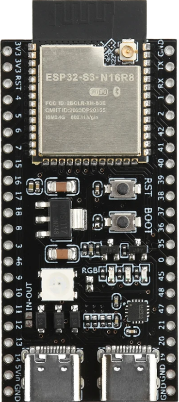
 Design with ESP32-S3 N16R8 in Cirkit Designer
Introduction
The ESP32-S3 N16R8 is a powerful microcontroller designed for advanced IoT applications and complex processing tasks. It features integrated Wi-Fi and Bluetooth connectivity, making it ideal for smart devices, home automation, wearable electronics, and industrial IoT systems. With 16MB of flash memory and 8MB of RAM, the ESP32-S3 N16R8 is well-suited for applications requiring high-speed data processing, machine learning, and real-time communication.
Explore Projects Built with ESP32-S3 N16R8
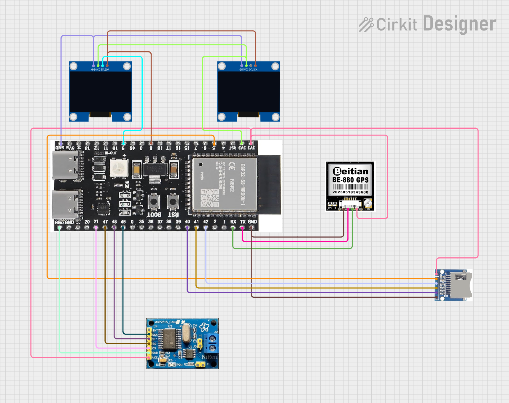 Open Project in Cirkit Designer
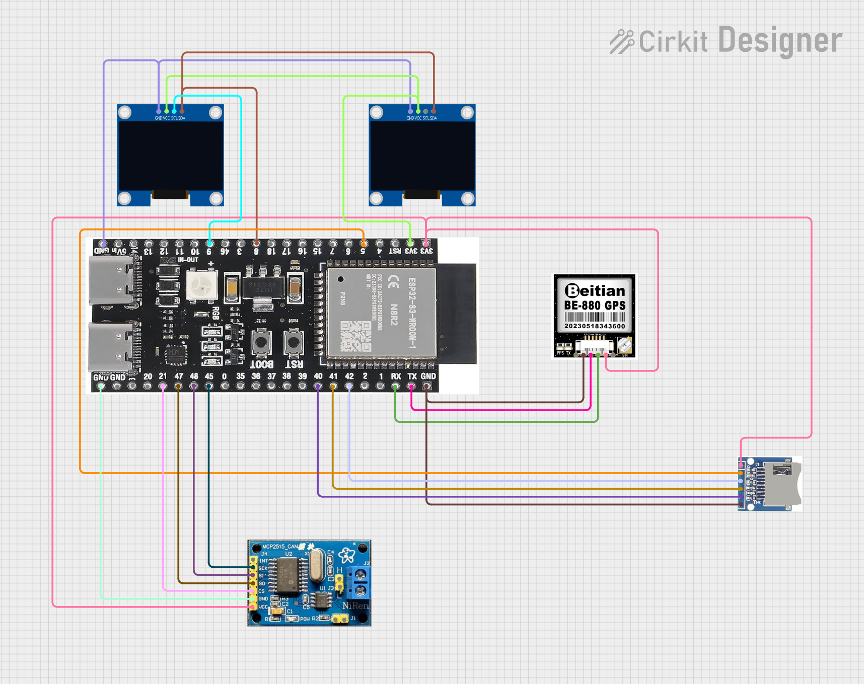 Open Project in Cirkit Designer
 Open Project in Cirkit Designer
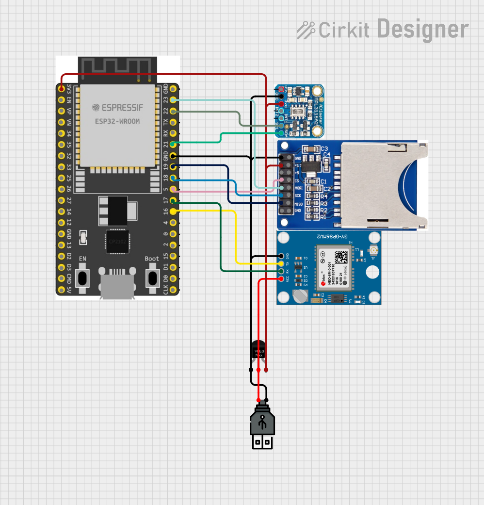 Open Project in Cirkit Designer
Explore Projects Built with ESP32-S3 N16R8
Open Project in Cirkit DesignerOpen Project in Cirkit DesignerOpen Project in Cirkit DesignerOpen Project in Cirkit DesignerCommon Applications
- IoT devices and smart home systems
- Wearable electronics
- Industrial automation and monitoring
- Machine learning and AI-based applications
- Wireless communication systems
- Multimedia streaming and processing
Technical Specifications
Key Technical Details
| Parameter | Specification |
|---|---|
| Microcontroller | ESP32-S3 |
| Flash Memory | 16MB |
| RAM | 8MB |
| Wi-Fi Standard | 802.11 b/g/n (2.4 GHz) |
| Bluetooth Standard | Bluetooth 5.0 (LE) |
| Operating Voltage | 3.0V - 3.6V |
| GPIO Pins | 45 |
| ADC Channels | 20 |
| DAC Channels | 2 |
| CPU | Dual-core Xtensa LX7 |
| Clock Speed | Up to 240 MHz |
| USB Support | USB OTG (On-The-Go) |
| Operating Temperature | -40°C to +85°C |
| Power Consumption | Ultra-low power modes available |
Pin Configuration and Descriptions
The ESP32-S3 N16R8 has a total of 45 GPIO pins, which can be configured for various functions. Below is a summary of the key pins:
| Pin Name | Functionality | Description |
|---|---|---|
| GPIO0 | Input/Output, Boot Mode Selection | Used for boot mode selection during reset |
| GPIO1 | UART TX | Transmit pin for UART communication |
| GPIO3 | UART RX | Receive pin for UART communication |
| GPIO18 | SPI CLK | Clock pin for SPI communication |
| GPIO19 | SPI MISO | Master In Slave Out for SPI |
| GPIO23 | SPI MOSI | Master Out Slave In for SPI |
| GPIO25 | DAC1 | Digital-to-Analog Converter Channel 1 |
| GPIO26 | DAC2 | Digital-to-Analog Converter Channel 2 |
| GPIO32 | ADC1 Channel 4 | Analog-to-Digital Converter input |
| GPIO33 | ADC1 Channel 5 | Analog-to-Digital Converter input |
| EN | Enable | Chip enable pin |
| 3V3 | Power Supply | 3.3V power input |
| GND | Ground | Ground connection |
For a complete pinout, refer to the official ESP32-S3 datasheet.
Usage Instructions
Using the ESP32-S3 N16R8 in a Circuit
- Power Supply: Ensure the ESP32-S3 is powered with a stable 3.3V supply. Avoid exceeding the maximum voltage of 3.6V to prevent damage.
- Boot Mode: To upload code, connect GPIO0 to GND during reset to enter bootloader mode.
- Peripherals: Connect peripherals (e.g., sensors, actuators) to the appropriate GPIO pins. Use pull-up or pull-down resistors as needed.
- Programming: The ESP32-S3 can be programmed using the Arduino IDE, ESP-IDF, or other compatible environments.
Example: Connecting to Wi-Fi with Arduino IDE
Below is an example code snippet to connect the ESP32-S3 to a Wi-Fi network using the Arduino IDE:
#include <WiFi.h> // Include the Wi-Fi library

// Replace with your network credentials
const char* ssid = "Your_SSID";       // Your Wi-Fi network name
const char* password = "Your_PASSWORD"; // Your Wi-Fi network password

void setup() {
  Serial.begin(115200); // Initialize serial communication at 115200 baud
  delay(1000);          // Wait for a moment before starting

  Serial.println("Connecting to Wi-Fi...");
  WiFi.begin(ssid, password); // Start connecting to Wi-Fi

  // Wait until the ESP32 is connected to the Wi-Fi network
  while (WiFi.status() != WL_CONNECTED) {
    delay(500);
    Serial.print(".");
  }

  Serial.println("\nConnected to Wi-Fi!");
  Serial.print("IP Address: ");
  Serial.println(WiFi.localIP()); // Print the assigned IP address
}

void loop() {
  // Add your main code here
}
Important Considerations
- GPIO Voltage Levels: Ensure all connected devices operate at 3.3V logic levels. Use level shifters if interfacing with 5V devices.
- Power Consumption: Use deep sleep or light sleep modes to reduce power consumption in battery-powered applications.
- Antenna Placement: For optimal Wi-Fi and Bluetooth performance, ensure the onboard antenna is not obstructed by metal objects or enclosures.
Troubleshooting and FAQs
Common Issues and Solutions
ESP32-S3 Not Connecting to Wi-Fi
- Cause: Incorrect SSID or password.
- Solution: Double-check the network credentials in your code.
- Tip: Ensure the Wi-Fi network operates on the 2.4 GHz band, as the ESP32-S3 does not support 5 GHz.
Code Upload Fails
- Cause: Incorrect boot mode or COM port not selected.
- Solution: Ensure GPIO0 is connected to GND during reset. Verify the correct COM port is selected in the Arduino IDE.
Random Resets or Instability
- Cause: Insufficient power supply or voltage fluctuations.
- Solution: Use a stable 3.3V power source with adequate current capacity (at least 500mA).
GPIO Pins Not Responding
- Cause: Incorrect pin configuration or conflicting functions.
- Solution: Check the pin configuration in your code and ensure no peripherals are using the same pins.
FAQs
Q: Can the ESP32-S3 N16R8 be used for machine learning applications?
A: Yes, the ESP32-S3 supports TensorFlow Lite Micro and other lightweight ML frameworks, making it suitable for edge AI applications.
Q: Does the ESP32-S3 support USB programming?
A: Yes, the ESP32-S3 features USB OTG, which can be used for programming and communication.
Q: How do I reduce power consumption in battery-powered projects?
A: Use the deep sleep or light sleep modes provided by the ESP32-S3. These modes significantly reduce power consumption by turning off unnecessary peripherals.
Q: Can I use the ESP32-S3 with a 5V power supply?
A: No, the ESP32-S3 operates at 3.3V. Use a voltage regulator to step down 5V to 3.3V if necessary.
For additional support, refer to the official ESP32-S3 documentation or community forums.