How to Use PicoBuck LED Driver: Examples, Pinouts, and Specs
Introduction
The PicoBuck LED Driver is a versatile and compact board designed for driving high-power LEDs with ease and efficiency. It is capable of controlling up to three LEDs in series, making it an ideal choice for a variety of LED lighting applications such as architectural lighting, task lighting, and DIY LED projects. Its simplicity and power make it a popular choice for hobbyists and professionals alike.
Explore Projects Built with PicoBuck LED Driver

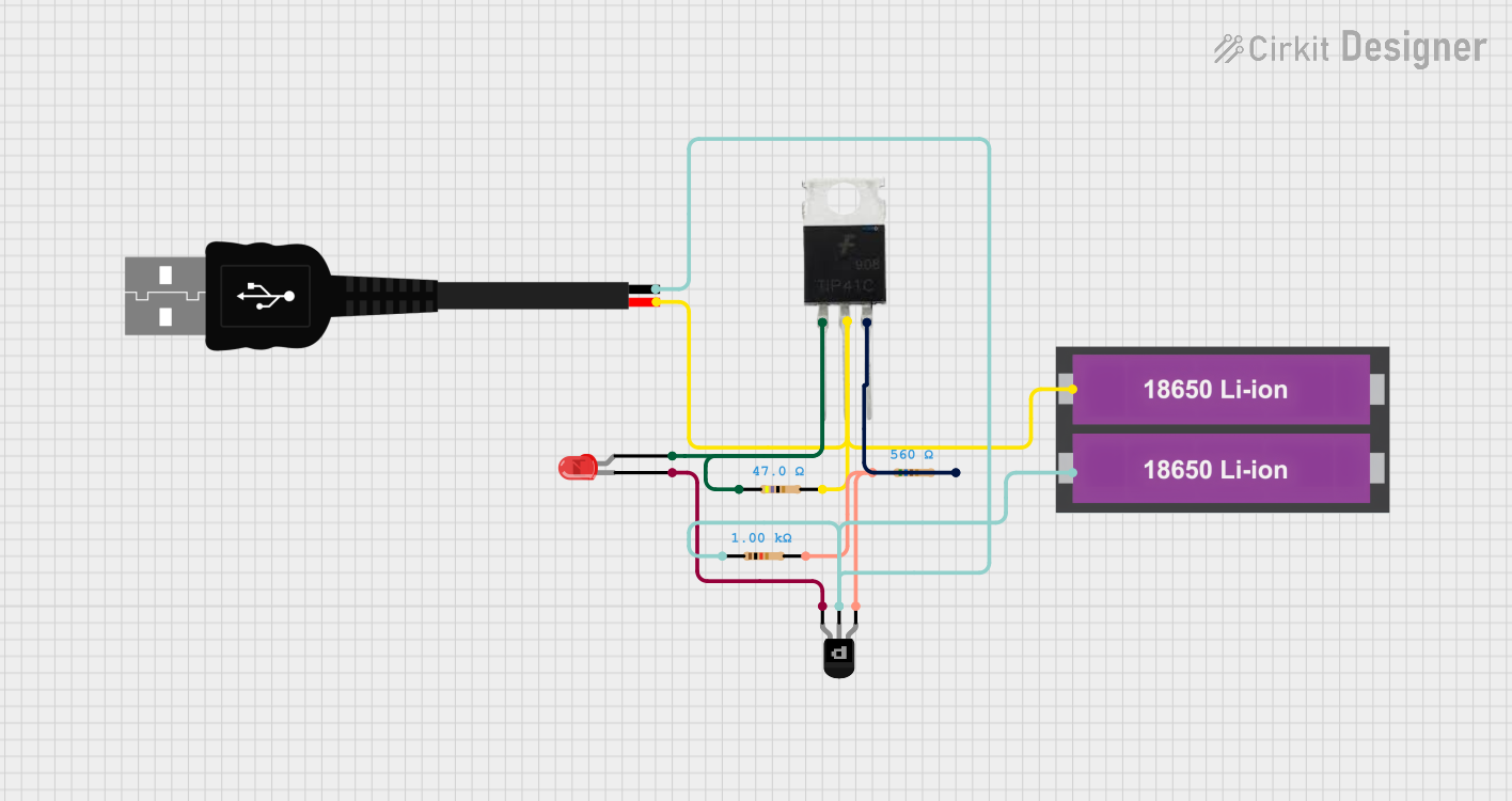
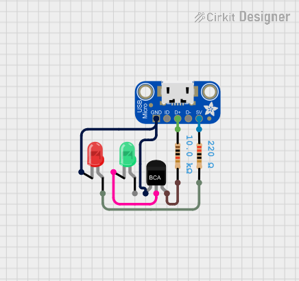
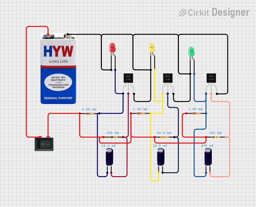
Explore Projects Built with PicoBuck LED Driver
Technical Specifications
Key Technical Details
- Input Voltage: 6V to 20V
- Output Current: Adjustable from 330mA to 660mA per channel
- Maximum Power Rating: 20W
- Number of Channels: 3
- Efficiency: Up to 95%
- PWM Dimming: Up to 20kHz
- Operating Temperature: -40°C to 85°C
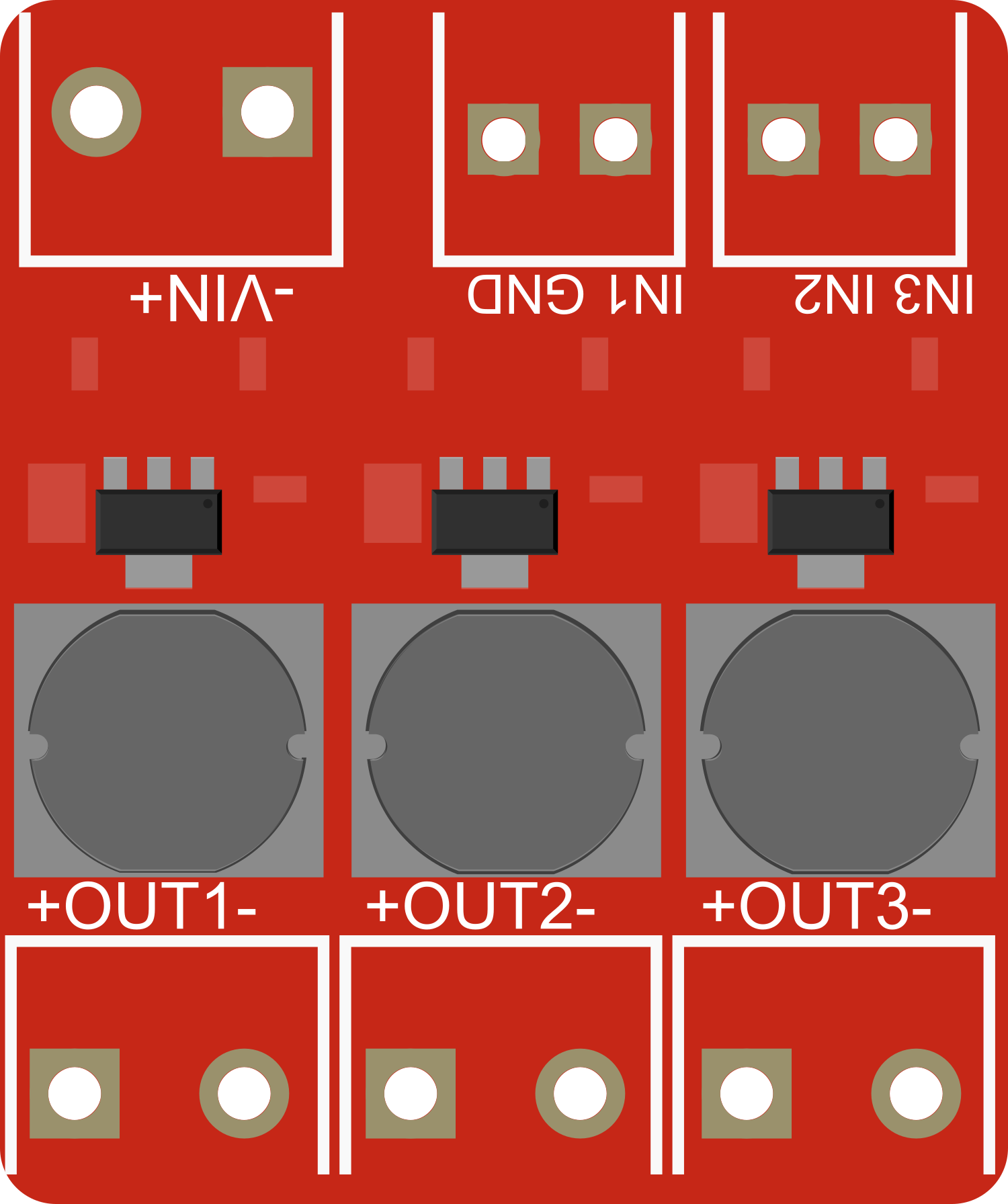
Pin Configuration and Descriptions
| Pin Number | Name | Description |
|---|---|---|
| 1 | VIN | Input voltage (6V to 20V) |
| 2 | GND | Ground connection |
| 3 | EN | Enable pin (active high) |
| 4 | CTRL | Control input for PWM dimming |
| 5 | OUT1 | LED output channel 1 |
| 6 | OUT2 | LED output channel 2 |
| 7 | OUT3 | LED output channel 3 |
Usage Instructions
How to Use the PicoBuck LED Driver in a Circuit
Connecting Power: Connect a power supply to the VIN and GND pins, ensuring that the voltage is within the specified range (6V to 20V).
Attaching LEDs: Connect your high-power LEDs to the OUT1, OUT2, and OUT3 channels, with the anode to the output pin and the cathode to the GND.
Setting Current Limit: Adjust the onboard potentiometers to set the desired current limit for each channel (330mA to 660mA).
Enabling the Driver: Apply a high signal to the EN pin to enable the driver. A low signal will turn off the output to the LEDs.
Dimming Control: Use the CTRL pin to apply a PWM signal for dimming the LEDs. The frequency can be up to 20kHz.
Important Considerations and Best Practices
- Ensure that the power supply voltage does not exceed the maximum input voltage rating.
- Always set the current limit to a safe level for your specific LEDs to prevent overheating and damage.
- Use proper heat sinking for the PicoBuck LED Driver and the LEDs to manage heat dissipation.
- When using PWM dimming, ensure that the frequency and duty cycle are within the specified limits for smooth operation.
Troubleshooting and FAQs
Common Issues and Solutions
- LEDs Not Lighting Up: Check the power supply connections and ensure that the EN pin is set high.
- Flickering LEDs: Verify that the PWM signal is within the correct frequency range and that the duty cycle is stable.
- Overheating: Ensure that adequate heat sinking is in place for both the driver and the LEDs.
FAQs
Q: Can I drive LEDs that require more than 660mA? A: No, the PicoBuck LED Driver is designed with a maximum current limit of 660mA per channel.
Q: Is it possible to chain multiple PicoBuck drivers together? A: Yes, you can chain multiple drivers to control more than three LEDs, but each driver must be powered and controlled independently.
Q: How do I adjust the current limit? A: Use a small screwdriver to adjust the onboard potentiometers corresponding to each channel.
Example Arduino Code for PWM Dimming
// Define the control pin for the PicoBuck LED Driver
const int pwmPin = 9; // Connect to the CTRL pin of the PicoBuck

void setup() {
  // Set the PWM pin as an output
  pinMode(pwmPin, OUTPUT);
}

void loop() {
  // Increase the brightness gradually
  for (int dutyCycle = 0; dutyCycle <= 255; dutyCycle++) {
    analogWrite(pwmPin, dutyCycle);
    delay(10);
  }
  // Decrease the brightness gradually
  for (int dutyCycle = 255; dutyCycle >= 0; dutyCycle--) {
    analogWrite(pwmPin, dutyCycle);
    delay(10);
  }
}
This example demonstrates how to gradually increase and decrease the brightness of the LEDs connected to the PicoBuck LED Driver using PWM dimming. The analogWrite function is used to send a PWM signal to the CTRL pin of the PicoBuck. The delay function is used to slow down the change in brightness for visibility.