How to Use RPLIDAR S2: Examples, Pinouts, and Specs
Introduction
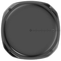
The RPLIDAR S2 by SLAMTEC is a high-performance 360-degree laser scanner designed for mapping, navigation, and obstacle detection in robotics. It uses laser triangulation technology to provide precise distance measurements and can generate detailed 2D maps of the surrounding environment. With its compact design and robust performance, the RPLIDAR S2 is ideal for applications such as autonomous vehicles, drones, robotic vacuum cleaners, and industrial automation.
Explore Projects Built with RPLIDAR S2
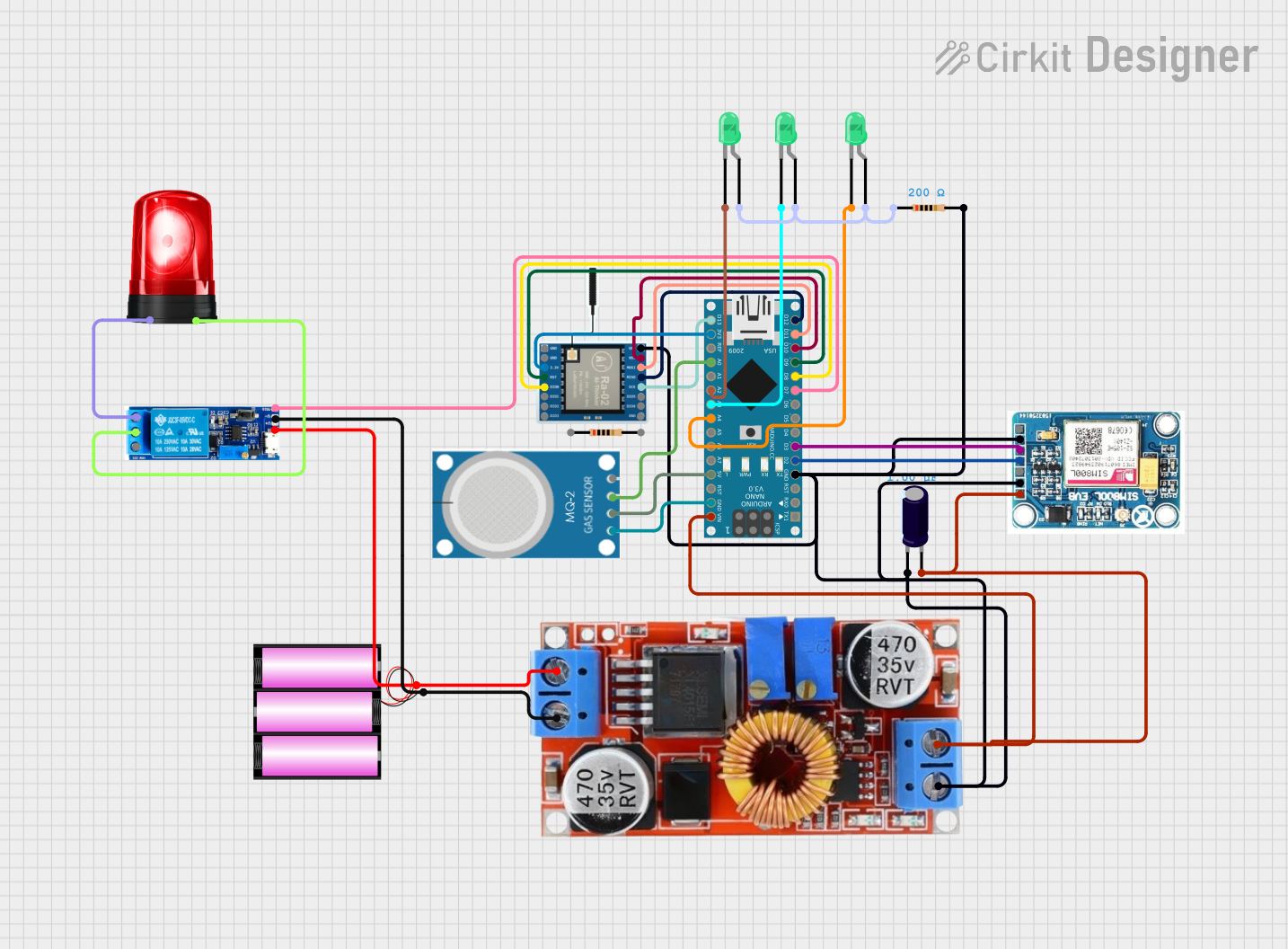

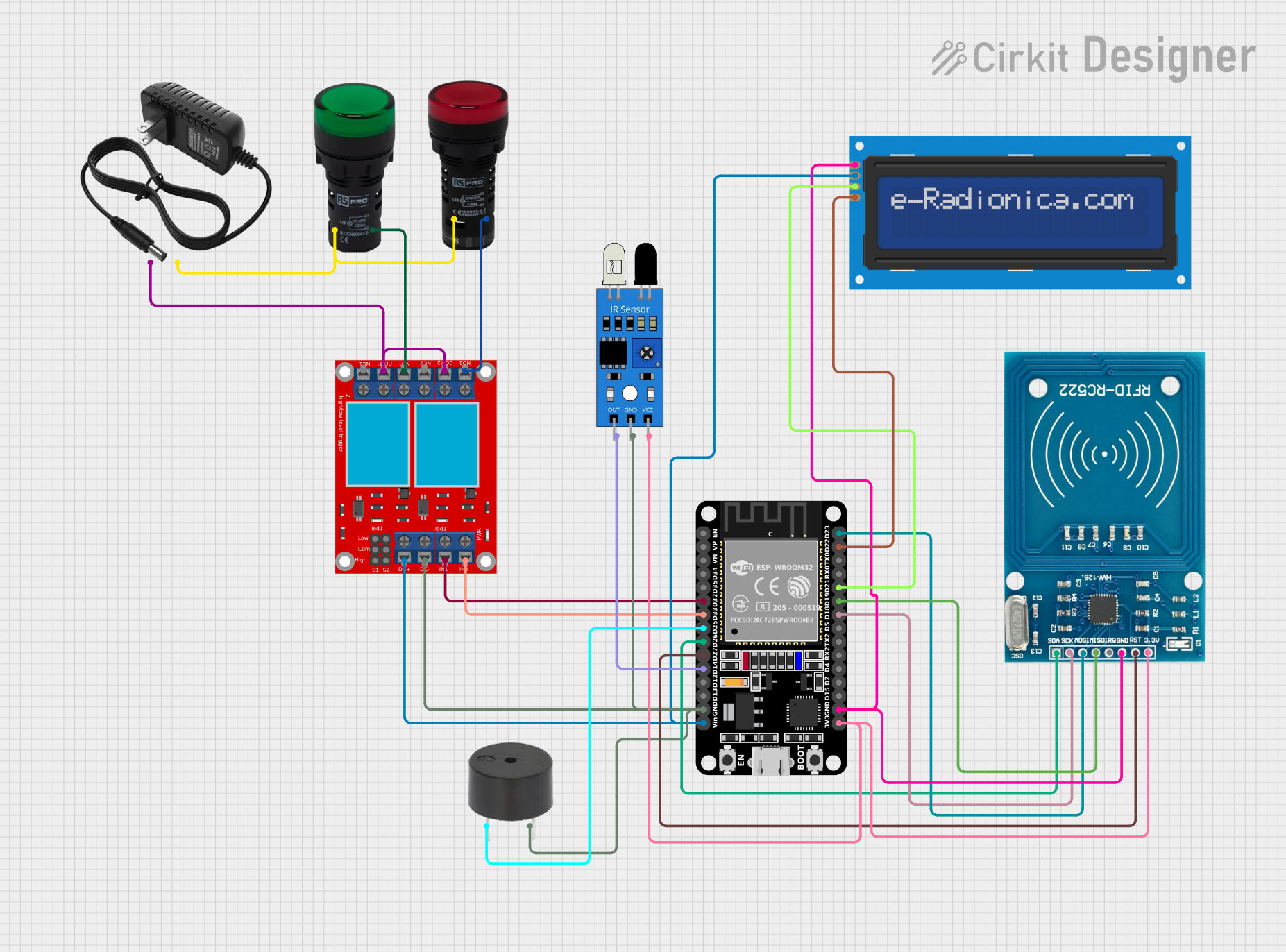
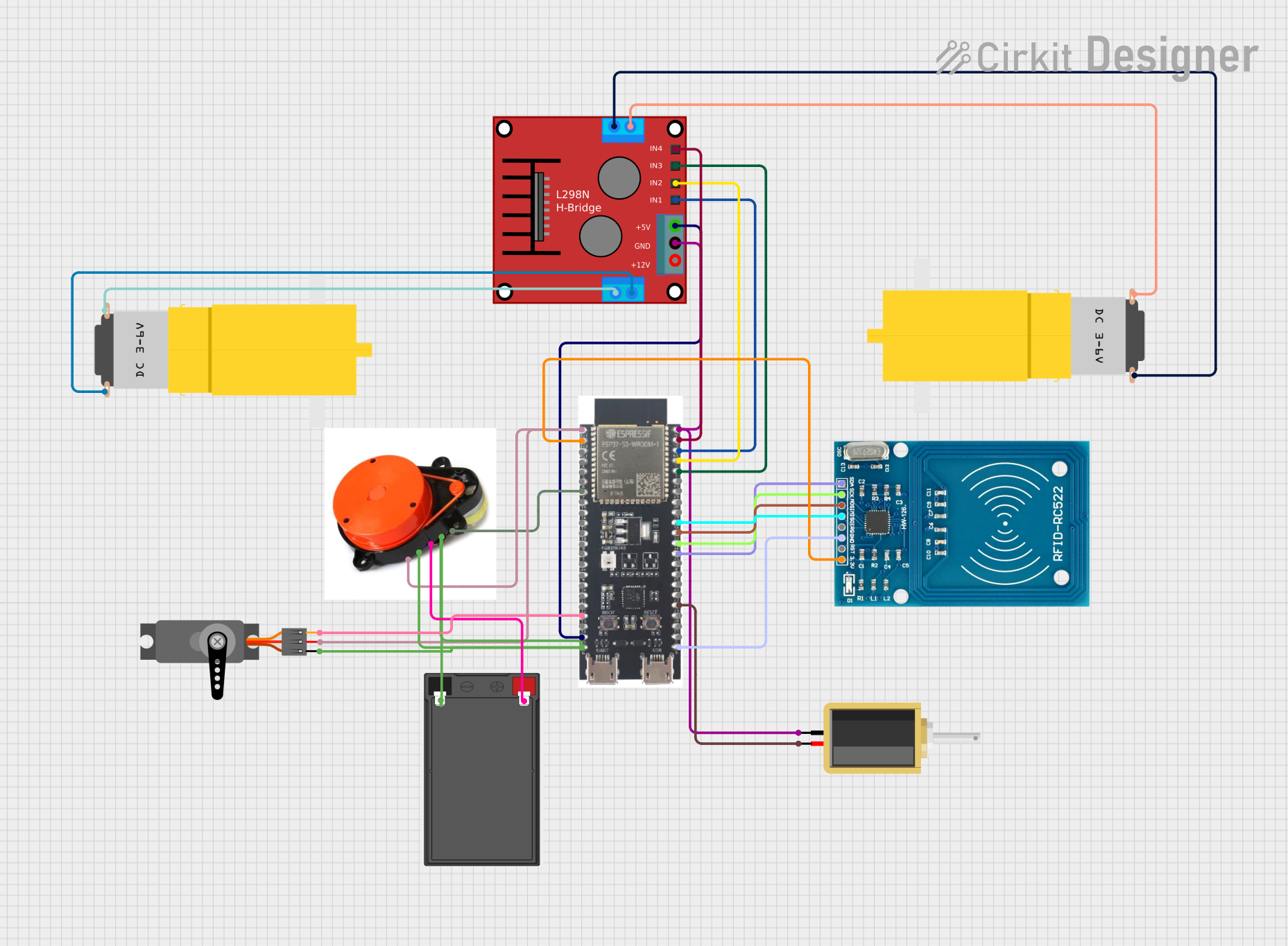
Explore Projects Built with RPLIDAR S2
Common Applications:
- Autonomous navigation for robots and drones
- Obstacle detection and avoidance
- Indoor and outdoor 2D mapping
- SLAM (Simultaneous Localization and Mapping) systems
- Industrial automation and safety systems
Technical Specifications
Key Specifications:
| Parameter | Value |
|---|---|
| Manufacturer | SLAMTEC |
| Model | RPLIDAR S2 |
| Measurement Range | 0.15 m to 30 m (indoor), 0.15 m to 20 m (outdoor) |
| Scanning Frequency | 10 Hz to 20 Hz |
| Angular Resolution | 0.45° to 0.9° |
| Field of View (FOV) | 360° |
| Distance Resolution | < 1% of the distance |
| Communication Interface | UART (3.3V TTL) |
| Power Supply Voltage | 5 V DC |
| Power Consumption | < 5 W |
| Dimensions | 79.2 mm (diameter) x 41.3 mm (height) |
| Weight | 190 g |
Pin Configuration:
The RPLIDAR S2 uses a 5-pin interface for communication and power. Below is the pinout description:
| Pin Number | Pin Name | Description |
|---|---|---|
| 1 | VCC | Power supply input (5 V DC) |
| 2 | GND | Ground |
| 3 | TX | UART Transmit (3.3V TTL) |
| 4 | RX | UART Receive (3.3V TTL) |
| 5 | MOTOCTL | Motor control signal (PWM input) |
Usage Instructions
Connecting the RPLIDAR S2 to a Microcontroller:
- Power Supply: Connect the VCC pin to a 5V DC power source and the GND pin to ground.
- UART Communication: Connect the TX pin of the RPLIDAR S2 to the RX pin of the microcontroller, and the RX pin of the RPLIDAR S2 to the TX pin of the microcontroller.
- Motor Control: Use the MOTOCTL pin to control the motor speed using a PWM signal. A typical PWM frequency of 10 kHz is recommended.
Example: Using RPLIDAR S2 with Arduino UNO
Below is an example of how to interface the RPLIDAR S2 with an Arduino UNO for basic data acquisition:
Wiring:
- VCC → Arduino 5V
- GND → Arduino GND
- TX → Arduino RX (Pin 0)
- RX → Arduino TX (Pin 1)
- MOTOCTL → Arduino PWM Pin (e.g., Pin 3)
Code:
#include <SoftwareSerial.h>

// Define pins for RPLIDAR communication
#define RPLIDAR_RX 0  // Arduino RX pin connected to RPLIDAR TX
#define RPLIDAR_TX 1  // Arduino TX pin connected to RPLIDAR RX
#define MOTOCTL_PIN 3 // PWM pin for motor control

SoftwareSerial rplidarSerial(RPLIDAR_RX, RPLIDAR_TX);

void setup() {
  // Initialize serial communication
  Serial.begin(115200); // For debugging
  rplidarSerial.begin(115200); // RPLIDAR communication baud rate

  // Initialize motor control pin
  pinMode(MOTOCTL_PIN, OUTPUT);
  analogWrite(MOTOCTL_PIN, 128); // Set motor speed (50% duty cycle)

  Serial.println("RPLIDAR S2 Initialized");
}

void loop() {
  // Check if data is available from RPLIDAR
  if (rplidarSerial.available()) {
    // Read and print data from RPLIDAR
    char data = rplidarSerial.read();
    Serial.print(data);
  }
}
Important Considerations:
- Ensure the RPLIDAR S2 is placed on a stable surface to avoid vibrations that may affect measurements.
- Avoid exposing the sensor to direct sunlight or reflective surfaces, as this may interfere with laser readings.
- Use a proper power supply to ensure stable operation, as voltage fluctuations can cause erratic behavior.
- The motor control signal (MOTOCTL) must be properly configured to maintain consistent scanning speed.
Troubleshooting and FAQs
Common Issues:
No Data Output:
- Cause: Incorrect wiring or baud rate mismatch.
- Solution: Verify the TX and RX connections and ensure the baud rate is set to 115200.
Inconsistent Measurements:
- Cause: Vibrations or reflective surfaces in the environment.
- Solution: Place the RPLIDAR on a stable surface and avoid reflective objects in the scanning area.
Motor Not Spinning:
- Cause: MOTOCTL pin not receiving a valid PWM signal.
- Solution: Check the PWM signal on the MOTOCTL pin and ensure it is within the recommended frequency range.
Short Measurement Range:
- Cause: Dust or dirt on the laser window.
- Solution: Clean the laser window with a soft, lint-free cloth.
FAQs:
Q: Can the RPLIDAR S2 be used outdoors?
- A: Yes, but the maximum range is reduced to 20 meters, and performance may be affected by strong sunlight.
Q: What is the lifespan of the RPLIDAR S2?
- A: The RPLIDAR S2 has a typical lifespan of over 10,000 hours of continuous operation.
Q: Can I use the RPLIDAR S2 with a Raspberry Pi?
- A: Yes, the RPLIDAR S2 can be connected to a Raspberry Pi using its UART interface or a USB-to-UART adapter.
Q: Is the RPLIDAR S2 compatible with ROS (Robot Operating System)?
- A: Yes, SLAMTEC provides ROS drivers for the RPLIDAR S2, making it easy to integrate into ROS-based systems.
This concludes the documentation for the RPLIDAR S2. For further details, refer to the official SLAMTEC user manual or contact their technical support.