How to Use Oscillscope: Examples, Pinouts, and Specs
Introduction
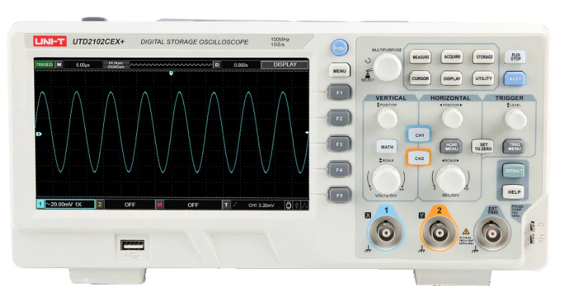
An oscilloscope is an electronic test instrument that graphically displays varying signal voltages, typically as a two-dimensional plot of one or more signals as a function of time. It is an essential tool for engineers, technicians, and hobbyists to analyze and debug electronic circuits. Oscilloscopes are widely used in fields such as electronics design, telecommunications, automotive diagnostics, and medical equipment testing.
Explore Projects Built with Oscillscope
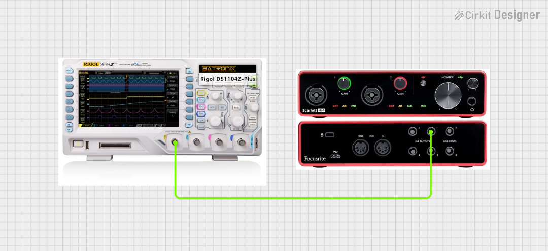

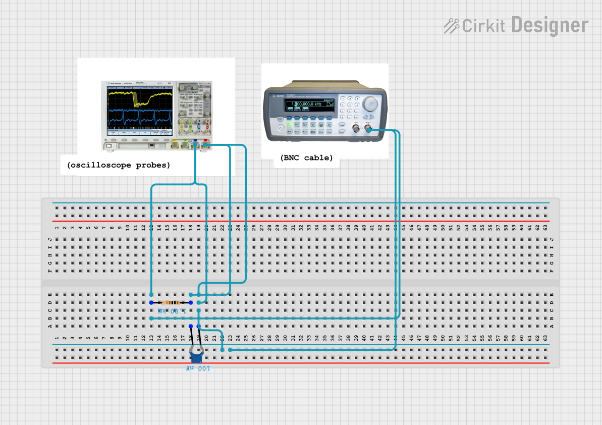
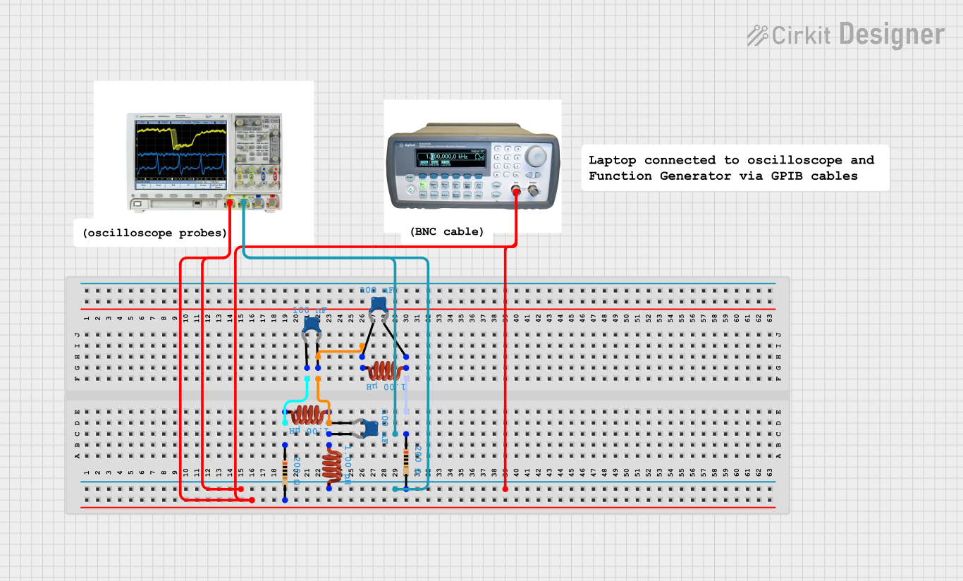
Explore Projects Built with Oscillscope
Common Applications and Use Cases
- Signal Analysis: Visualizing waveforms to measure amplitude, frequency, and phase.
- Circuit Debugging: Identifying faults in electronic circuits.
- Embedded Systems Development: Monitoring digital and analog signals in microcontroller-based systems.
- Power Electronics: Measuring power supply ripple, noise, and transient responses.
- Audio Engineering: Analyzing audio signals for distortion or interference.
Technical Specifications
Oscilloscopes come in various types, such as analog, digital, and mixed-signal. Below are the general technical specifications for a typical digital oscilloscope:
Key Technical Details
| Parameter | Description |
|---|---|
| Bandwidth | 20 MHz to 1 GHz (varies by model) |
| Sample Rate | Up to 5 GS/s (Giga-samples per second) |
| Input Channels | 2 to 4 channels (common models) |
| Vertical Resolution | 8-bit to 12-bit (higher resolution for advanced models) |
| Input Impedance | 1 MΩ or 50 Ω (selectable) |
| Voltage Range | ±5 mV to ±50 V (varies by model) |
| Time Base Range | 1 ns/div to 50 s/div |
| Display | LCD or TFT screen, typically 7 inches or larger |
| Connectivity | USB, Ethernet, or Wi-Fi for data transfer and remote control |
| Trigger Modes | Edge, Pulse, Video, Slope, and more |
Input Channel Pin Configuration
| Pin Name | Description |
|---|---|
| CH1 | Input for Channel 1 signal measurement |
| CH2 | Input for Channel 2 signal measurement (if available) |
| Ground | Common ground connection for signal reference |
| Probe Compensation | Used to calibrate the oscilloscope probe for accurate measurements |
Usage Instructions
How to Use the Oscilloscope in a Circuit
- Connect the Probe: Attach the oscilloscope probe to the input channel (e.g., CH1). Connect the probe's ground clip to the circuit's ground.
- Set the Voltage Range: Adjust the vertical scale (volts/div) to match the expected signal amplitude.
- Set the Time Base: Adjust the horizontal scale (time/div) to display the desired portion of the signal.
- Trigger the Signal: Configure the trigger settings to stabilize the waveform on the display.
- Analyze the Waveform: Use the measurement tools to determine parameters such as frequency, amplitude, and rise time.
Important Considerations and Best Practices
- Probe Calibration: Always calibrate the probe using the oscilloscope's built-in compensation signal to ensure accurate measurements.
- Bandwidth Selection: Choose an oscilloscope with a bandwidth at least 5 times higher than the highest frequency of the signal you want to measure.
- Avoid Overloading: Do not exceed the input voltage range of the oscilloscope to prevent damage.
- Grounding: Ensure proper grounding to avoid noise and interference in the measurements.
- Use Proper Probes: Use probes with appropriate attenuation (e.g., 10x) for high-voltage signals.
Example: Using an Oscilloscope with an Arduino UNO
To visualize a PWM signal generated by an Arduino UNO, follow these steps:
- Connect the oscilloscope probe to the Arduino's PWM output pin (e.g., Pin 9).
- Connect the probe's ground clip to the Arduino's GND pin.
- Upload the following code to the Arduino:
// Arduino code to generate a PWM signal on Pin 9
void setup() {
  pinMode(9, OUTPUT); // Set Pin 9 as an output
  analogWrite(9, 128); // Generate a 50% duty cycle PWM signal
}

void loop() {
  // No code needed in the loop for this example
}
- Set the oscilloscope's vertical scale to 2V/div and the time base to 1 ms/div.
- Adjust the trigger level to stabilize the waveform and observe the PWM signal.
Troubleshooting and FAQs
Common Issues and Solutions
| Issue | Possible Cause | Solution |
|---|---|---|
| No waveform displayed | Incorrect probe connection | Verify probe is connected to the correct pin |
| Unstable waveform | Improper trigger settings | Adjust the trigger level and mode |
| Distorted signal | Incorrect probe compensation | Calibrate the probe using the compensation signal |
| Excessive noise in waveform | Poor grounding or external interference | Ensure proper grounding and minimize noise sources |
| Signal exceeds display range | Voltage range not set correctly | Adjust the vertical scale (volts/div) |
FAQs
Can I use an oscilloscope to measure DC signals? Yes, oscilloscopes can measure both DC and AC signals. Set the input coupling to "DC" for DC measurements.
What is the difference between analog and digital oscilloscopes? Analog oscilloscopes display waveforms in real-time using a CRT, while digital oscilloscopes sample and process signals digitally, offering advanced features like storage and analysis.
How do I choose the right oscilloscope for my application? Consider factors such as bandwidth, sample rate, number of channels, and additional features like protocol decoding or connectivity options.
Can I damage my oscilloscope by measuring high voltages? Yes, exceeding the input voltage range can damage the oscilloscope. Use appropriate probes with attenuation for high-voltage measurements.
By following this documentation, users can effectively utilize an oscilloscope for a wide range of applications, ensuring accurate and reliable signal analysis.