How to Use TMC2208: Examples, Pinouts, and Specs
Introduction
The TMC2208 is a high-performance stepper motor driver designed for smooth, precise, and silent operation. It is widely used in applications requiring low noise and high efficiency, such as 3D printers, CNC machines, and robotics. The TMC2208 supports microstepping, enabling fine control of stepper motors, and includes advanced features like stealthChop for silent operation and coolStep for energy-efficient performance.
Explore Projects Built with TMC2208


Explore Projects Built with TMC2208
Common Applications:
- 3D printers for precise and quiet motor control
- CNC machines for smooth and accurate motion
- Robotics for energy-efficient and silent operation
- Automated systems requiring low-noise stepper motor drivers
Technical Specifications
The TMC2208 offers a range of features and specifications that make it suitable for demanding applications. Below are the key technical details:
Key Specifications:
- Operating Voltage (V_M): 4.75V to 36V
- Logic Voltage (V_IO): 3.3V or 5V
- Maximum Motor Current: 1.2A RMS (2.0A peak)
- Microstepping Resolution: Up to 256 microsteps per full step
- Control Modes: UART or standalone mode
- Features: stealthChop, spreadCycle, coolStep, stallGuard
- Operating Temperature: -40°C to +125°C
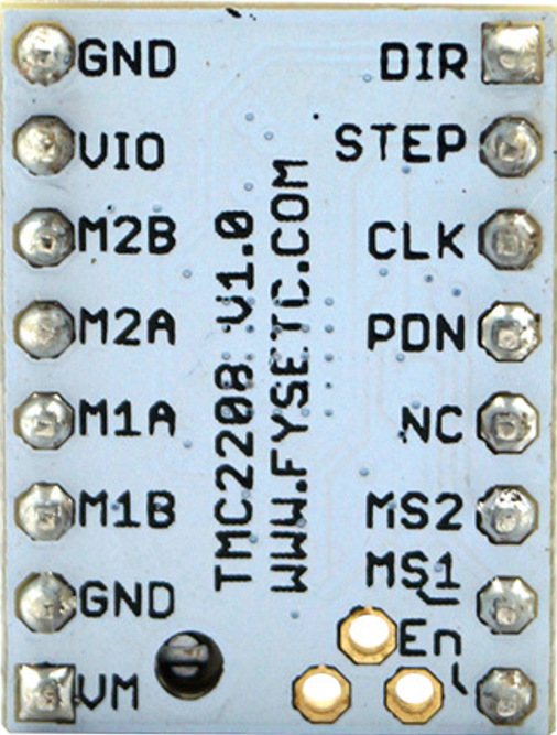
Pin Configuration and Descriptions:
The TMC2208 is typically available in a 16-pin package. Below is the pinout and description:
| Pin | Name | Description |
|---|---|---|
| 1 | GND | Ground connection for power and logic. |
| 2 | V_M | Motor power supply (4.75V to 36V). |
| 3 | V_IO | Logic voltage input (3.3V or 5V). |
| 4 | ENN | Enable pin (active low). |
| 5 | MS1 | Microstep resolution selection pin 1. |
| 6 | MS2 | Microstep resolution selection pin 2. |
| 7 | STEP | Step pulse input for motor control. |
| 8 | DIR | Direction control input. |
| 9 | UART | UART interface for configuration and control. |
| 10 | DIAG | Diagnostic output (e.g., stall detection). |
| 11 | INDEX | Index output for step position indication. |
| 12 | VREF | Reference voltage input for current setting. |
| 13 | NC | Not connected. |
| 14 | NC | Not connected. |
| 15 | GND | Ground connection for power and logic. |
| 16 | V_M | Motor power supply (4.75V to 36V). |
Usage Instructions
The TMC2208 can be used in either standalone mode or UART mode, depending on the application requirements. Below are the steps and considerations for using the TMC2208 in a circuit.
Using the TMC2208 in a Circuit:
Power Supply:
- Connect the motor power supply (4.75V to 36V) to the V_M pin.
- Provide a logic voltage (3.3V or 5V) to the V_IO pin.
- Ensure proper decoupling capacitors are placed near the V_M and V_IO pins.
Microstepping Configuration:
- Use the MS1 and MS2 pins to set the desired microstepping resolution.
- For example:
- MS1 = LOW, MS2 = LOW: Full step
- MS1 = HIGH, MS2 = LOW: Half step
- MS1 = HIGH, MS2 = HIGH: 1/16 step
Control Signals:
- Connect the STEP pin to a microcontroller or pulse generator for step control.
- Use the DIR pin to set the motor's rotation direction.
UART Mode (Optional):
- Connect the UART pin to a microcontroller for advanced configuration and control.
- Use a UART library or protocol to send commands to the TMC2208.
Cooling:
- Ensure proper heat dissipation by using a heatsink or fan if the driver operates at high currents.
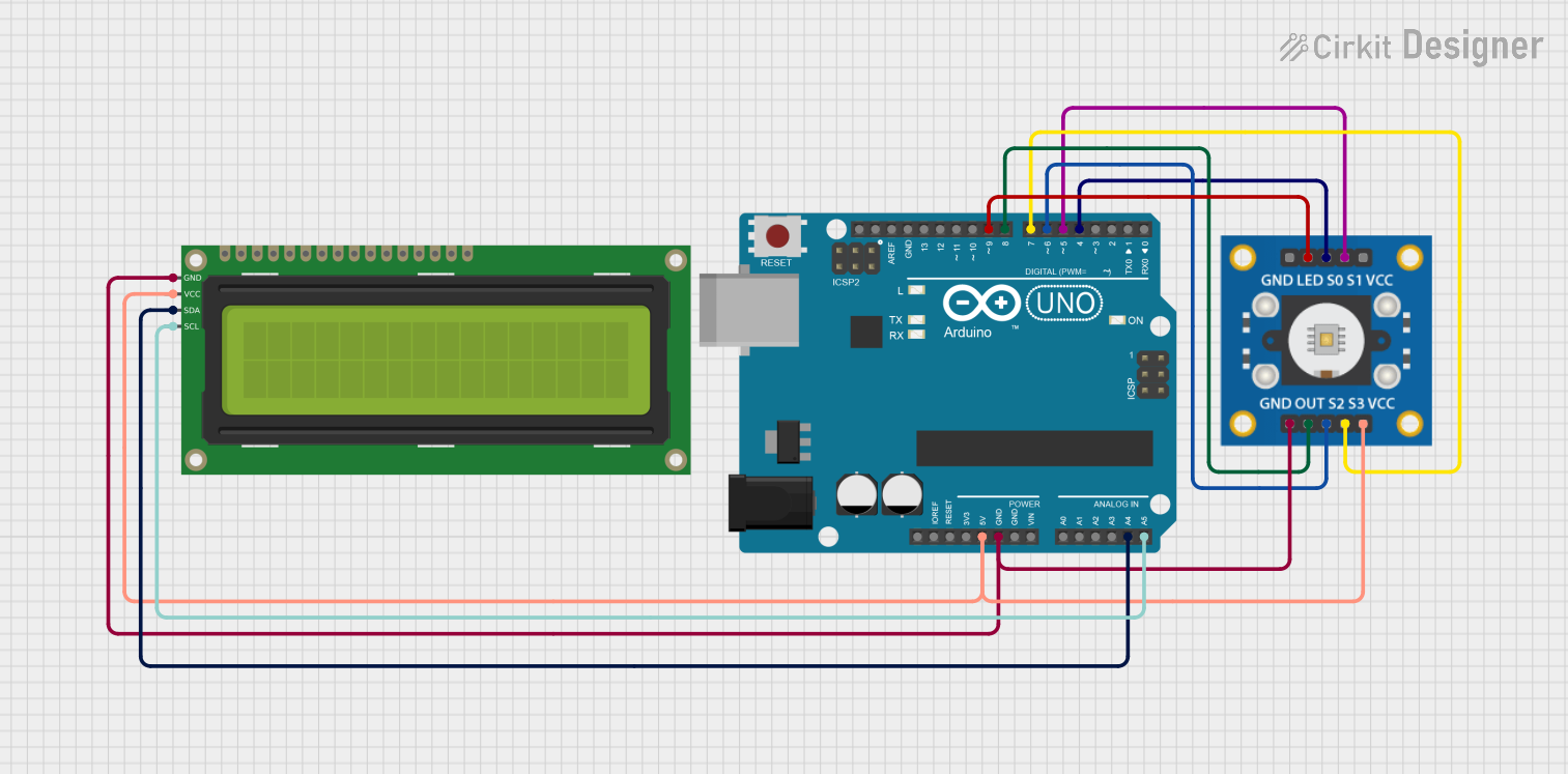
Example: Connecting TMC2208 to Arduino UNO
Below is an example of how to connect and control the TMC2208 using an Arduino UNO in UART mode:
Circuit Connections:
- TMC2208 V_M to 12V power supply
- TMC2208 V_IO to Arduino 5V
- TMC2208 GND to Arduino GND
- TMC2208 STEP to Arduino digital pin 3
- TMC2208 DIR to Arduino digital pin 4
- TMC2208 UART to Arduino digital pin 2 (via a voltage divider if needed)
Arduino Code:
#include <TMCStepper.h>

// Define pins for TMC2208
#define DIR_PIN 4   // Direction pin
#define STEP_PIN 3  // Step pin
#define SERIAL_PORT Serial  // UART port for TMC2208
#define DRIVER_ADDRESS 0b00  // TMC2208 driver address (default)

// Initialize TMC2208 driver
TMC2208Stepper driver(&SERIAL_PORT, DRIVER_ADDRESS);

void setup() {
  // Initialize serial communication for UART
  SERIAL_PORT.begin(115200);  // UART baud rate for TMC2208
  driver.begin();             // Initialize TMC2208 driver
  driver.toff(5);             // Enable driver
  driver.rms_current(800);    // Set motor current to 800mA
  driver.microsteps(16);      // Set microstepping to 1/16
  pinMode(DIR_PIN, OUTPUT);
  pinMode(STEP_PIN, OUTPUT);
}

void loop() {
  digitalWrite(DIR_PIN, HIGH);  // Set direction
  for (int i = 0; i < 200; i++) {
    digitalWrite(STEP_PIN, HIGH);  // Generate step pulse
    delayMicroseconds(500);        // Delay for step timing
    digitalWrite(STEP_PIN, LOW);
    delayMicroseconds(500);
  }
  delay(1000);  // Wait before changing direction
  digitalWrite(DIR_PIN, LOW);  // Change direction
}
Best Practices:
- Use proper decoupling capacitors to reduce noise and ensure stable operation.
- Avoid exceeding the maximum current and voltage ratings to prevent damage.
- Use a heatsink or active cooling for high-current applications.
Troubleshooting and FAQs
Common Issues and Solutions:
Motor Not Moving:
- Check the power supply connections to V_M and V_IO.
- Verify the STEP and DIR signals from the microcontroller.
- Ensure the motor is properly connected to the driver.
Overheating:
- Use a heatsink or fan to dissipate heat.
- Reduce the motor current using the VREF pin or UART configuration.
Noisy Operation:
- Enable stealthChop mode for silent operation.
- Check for loose connections or insufficient decoupling capacitors.
UART Communication Fails:
- Verify the UART connections and baud rate.
- Ensure the correct driver address is used in the code.
FAQs:
Q: Can the TMC2208 operate without a microcontroller?
A: Yes, the TMC2208 can operate in standalone mode using the MS1 and MS2 pins for microstepping configuration.Q: What is the maximum microstepping resolution?
A: The TMC2208 supports up to 256 microsteps per full step.Q: How do I enable stealthChop mode?
A: stealthChop is enabled by default in UART mode. For standalone mode, refer to the datasheet for configuration details.Q: Can I use the TMC2208 with a 24V power supply?
A: Yes, the TMC2208 supports motor power supply voltages up to 36V. Ensure proper cooling for high-voltage operation.