How to Use Pololu S18V20F12 12V Step Up/Step Down: Examples, Pinouts, and Specs
Introduction
The Pololu S18V20F12 is a highly versatile DC-DC converter designed to provide a stable 12V output from a wide range of input voltages. This step-up/step-down regulator is ideal for applications where the input voltage may vary above or below the desired output voltage. Its compact design and high efficiency make it suitable for powering a variety of electronic devices, including sensors, microcontrollers, and small motors.
Explore Projects Built with Pololu S18V20F12 12V Step Up/Step Down

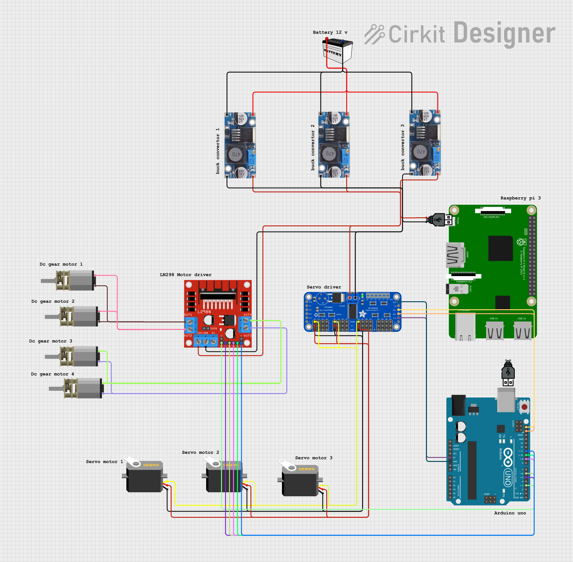

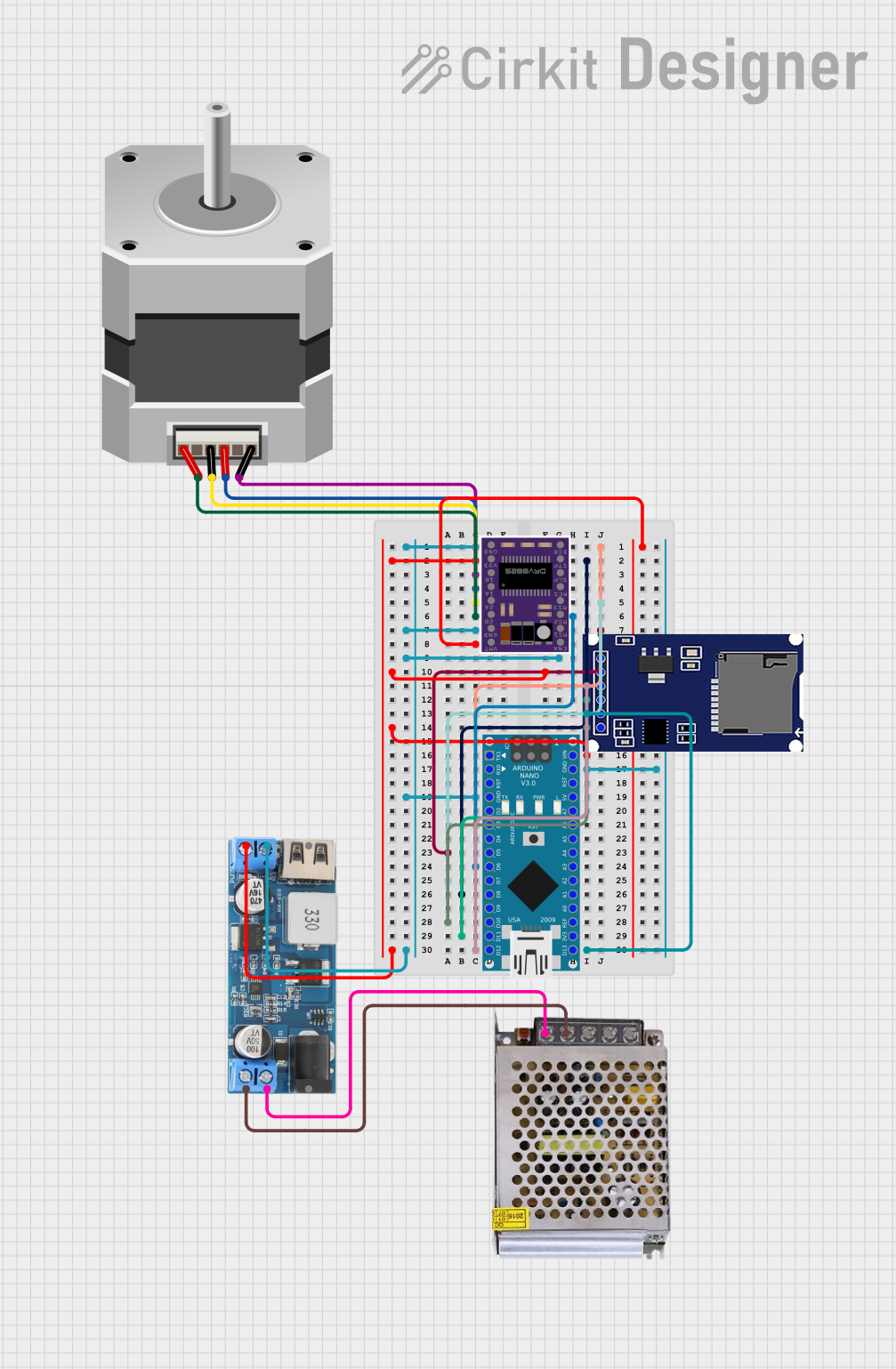
Explore Projects Built with Pololu S18V20F12 12V Step Up/Step Down
Common Applications and Use Cases
- Powering 12V devices from batteries with varying voltage levels (e.g., LiPo, NiMH).
- Stabilizing voltage in automotive or solar-powered systems.
- Supplying power to microcontrollers, sensors, and communication modules.
- Robotics and portable electronics requiring a reliable 12V source.
Technical Specifications
The following table outlines the key technical details of the Pololu S18V20F12:
| Parameter | Value |
|---|---|
| Output Voltage | 12V (fixed) |
| Input Voltage Range | 2.8V to 32V |
| Maximum Output Current | 2A (continuous, depending on input voltage) |
| Efficiency | Up to 90% |
| Switching Frequency | ~400 kHz |
| Dimensions | 24.9 mm × 25.4 mm × 3.8 mm |
| Weight | 3.5 g |
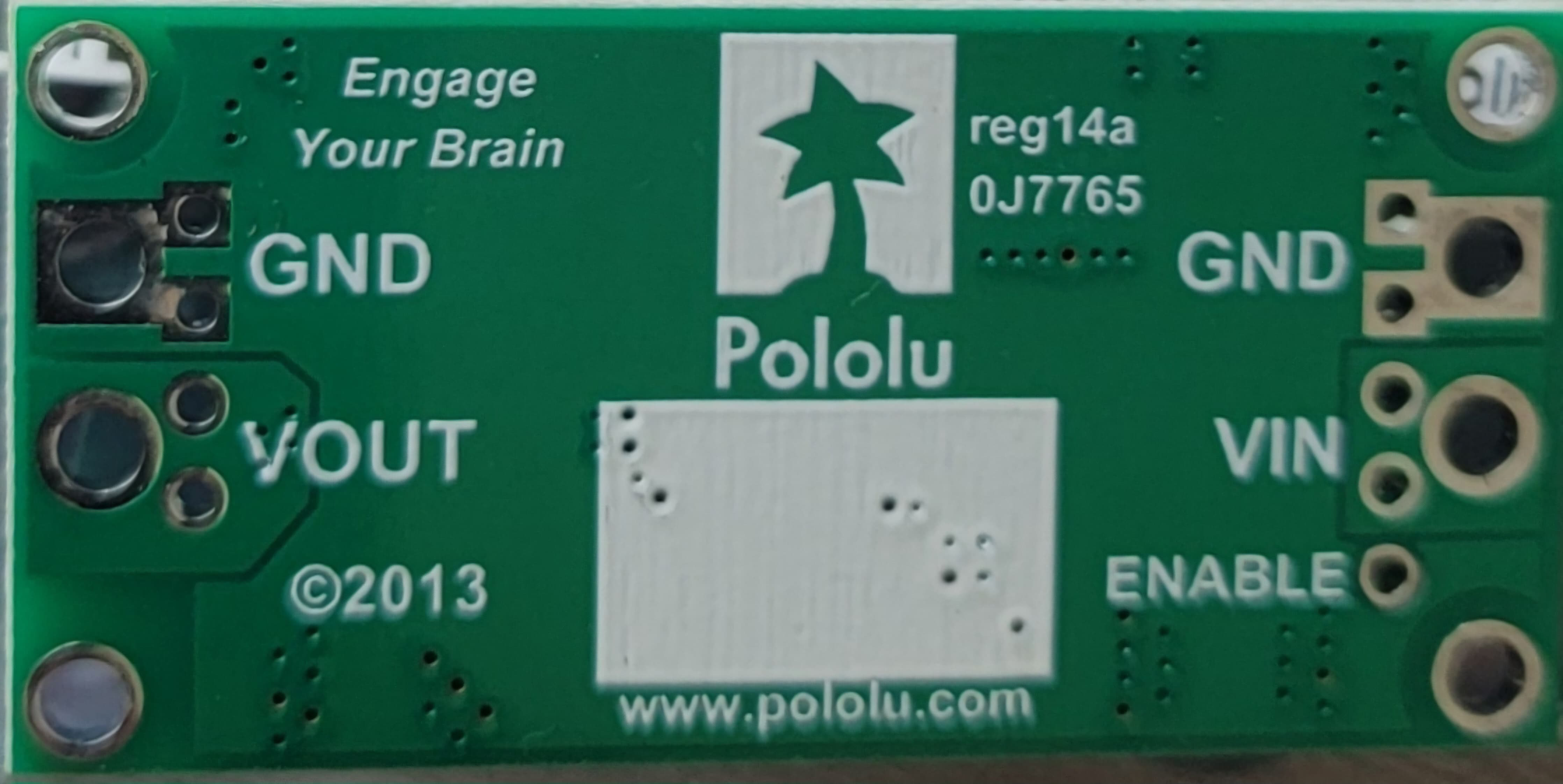
Pin Configuration and Descriptions
The Pololu S18V20F12 has six pins for easy integration into circuits. The table below describes each pin:
| Pin Name | Description |
|---|---|
| VIN | Input voltage pin (2.8V to 32V). Connect to the positive terminal of the power source. |
| GND | Ground pin. Connect to the negative terminal of the power source. |
| VOUT | Regulated 12V output pin. Connect to the load requiring 12V. |
| SHDN | Shutdown pin. Drive low (0V) to disable the regulator; leave floating or high to enable. |
| PG | Power good indicator. Outputs high when the output voltage is in regulation. |
| FB | Feedback pin. Used for advanced configurations (leave unconnected for default). |
Usage Instructions
How to Use the Component in a Circuit
Connect the Input Voltage:
- Connect the VIN pin to the positive terminal of your power source (e.g., battery or power supply).
- Connect the GND pin to the negative terminal of your power source.
Connect the Output Voltage:
- Connect the VOUT pin to the positive terminal of your load (e.g., a 12V device).
- Ensure the load's ground is connected to the GND pin.
Optional Connections:
- Use the SHDN pin to enable or disable the regulator. Leave it floating or connect it to VIN to enable the regulator. Pull it to GND to disable it.
- The PG pin can be used to monitor the output voltage status. It outputs a high signal when the output is stable.
- The FB pin is for advanced users who need to adjust the feedback loop. For standard operation, leave it unconnected.
Power On:
- Once all connections are secure, power on the input source. The regulator will provide a stable 12V output.
Important Considerations and Best Practices
- Input Voltage Range: Ensure the input voltage stays within the 2.8V to 32V range to avoid damaging the regulator.
- Heat Dissipation: At high currents, the regulator may generate heat. Consider adding a heatsink or improving airflow if the regulator becomes too warm.
- Current Limitations: The maximum output current depends on the input voltage. For example, at lower input voltages, the regulator may not provide the full 2A output.
- Capacitors: Add input and output capacitors close to the regulator to improve stability and reduce noise. A 10 µF capacitor is recommended on both VIN and VOUT.
Example: Using with an Arduino UNO
The Pololu S18V20F12 can be used to power an Arduino UNO from a battery. Below is an example circuit and code:
Circuit Connections
- Connect the VIN pin to the positive terminal of a 9V battery.
- Connect the GND pin to the negative terminal of the battery.
- Connect the VOUT pin to the Arduino UNO's VIN pin.
- Connect the GND pin to the Arduino UNO's GND pin.
Arduino Code Example
// Example code to blink an LED connected to pin 13 on the Arduino UNO
// Ensure the Pololu S18V20F12 is providing a stable 12V to the Arduino's VIN pin

void setup() {
  pinMode(13, OUTPUT); // Set pin 13 as an output
}

void loop() {
  digitalWrite(13, HIGH); // Turn the LED on
  delay(1000);            // Wait for 1 second
  digitalWrite(13, LOW);  // Turn the LED off
  delay(1000);            // Wait for 1 second
}
Troubleshooting and FAQs
Common Issues and Solutions
No Output Voltage:
- Check the input voltage. Ensure it is within the 2.8V to 32V range.
- Verify that the SHDN pin is not pulled low. Leave it floating or connect it to VIN.
Output Voltage is Unstable:
- Add capacitors (e.g., 10 µF) close to the VIN and VOUT pins to improve stability.
- Ensure the input power source can supply sufficient current.
Regulator Overheating:
- Reduce the load current if possible.
- Improve cooling by adding a heatsink or increasing airflow around the regulator.
PG Pin Not High:
- Check the load and ensure it is not drawing more current than the regulator can provide.
- Verify that the input voltage is stable and within range.
FAQs
Q: Can I adjust the output voltage?
A: No, the Pololu S18V20F12 provides a fixed 12V output. For adjustable output, consider other Pololu regulators.
Q: What happens if the input voltage exceeds 32V?
A: Exceeding 32V can damage the regulator. Use a voltage clamp or protection circuit to prevent overvoltage.
Q: Can I use this regulator with a solar panel?
A: Yes, as long as the solar panel's output voltage stays within the 2.8V to 32V range and provides sufficient current.
Q: Is reverse polarity protection included?
A: No, the regulator does not have built-in reverse polarity protection. Use a diode or other protection circuit to prevent damage.