
How to Use RS485 to USB: Examples, Pinouts, and Specs
 Design with RS485 to USB in Cirkit Designer
Introduction
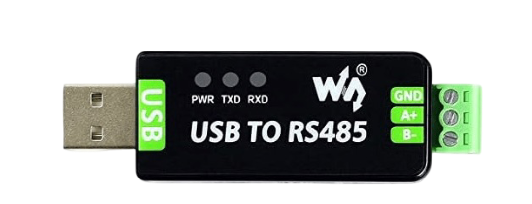
The RS485 to USB converter, manufactured by Wiki, is a versatile device that bridges the gap between RS485 serial communication and USB interfaces. It enables seamless data transfer between devices that use the RS485 communication standard and modern systems equipped with USB ports. This converter is widely used in industrial automation, data acquisition systems, and other applications requiring reliable serial communication over long distances.
Explore Projects Built with RS485 to USB
 Open Project in Cirkit Designer
 Open Project in Cirkit Designer
 Open Project in Cirkit Designer
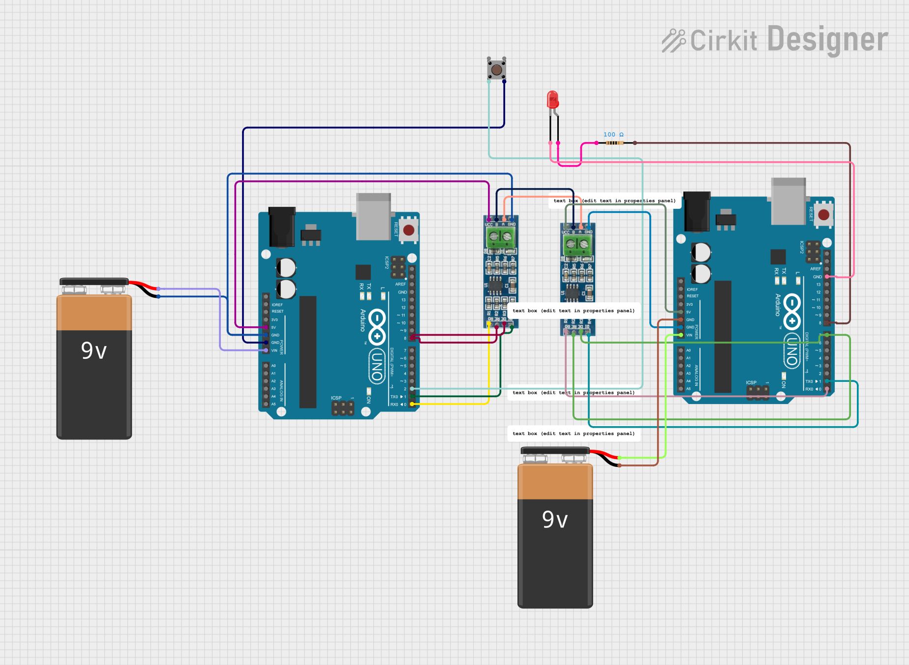 Open Project in Cirkit Designer
Explore Projects Built with RS485 to USB
Open Project in Cirkit DesignerOpen Project in Cirkit DesignerOpen Project in Cirkit DesignerOpen Project in Cirkit DesignerCommon Applications and Use Cases
- Industrial automation systems for connecting RS485-enabled devices to computers.
- Data acquisition systems for monitoring and controlling sensors or actuators.
- Home automation systems for integrating RS485-based devices with modern USB-enabled controllers.
- Debugging and testing RS485 communication protocols using a PC or laptop.
Technical Specifications
The RS485 to USB converter is designed to provide reliable and efficient communication. Below are its key technical details:
General Specifications
| Parameter | Value |
|---|---|
| Manufacturer | Wiki |
| Communication Protocol | RS485 to USB |
| USB Standard | USB 2.0 (compatible with USB 1.1) |
| Baud Rate | 300 bps to 3 Mbps |
| Operating Voltage | 5V (via USB port) |
| Power Consumption | < 100 mA |
| Operating Temperature | -40°C to 85°C |
| Dimensions | 60mm x 20mm x 10mm |
Pin Configuration and Descriptions
The RS485 to USB converter typically has the following pinouts for the RS485 interface:
| Pin Name | Description |
|---|---|
| A (D+) | RS485 Data Line Positive (Non-inverting signal) |
| B (D-) | RS485 Data Line Negative (Inverting signal) |
| GND | Ground (Common reference for RS485 signals) |
The USB interface connects directly to a USB port on a computer or other USB-enabled device.
Usage Instructions
How to Use the RS485 to USB Converter in a Circuit
Connect the RS485 Device:
- Connect the
A (D+)pin of the RS485 device to theApin of the converter. - Connect the
B (D-)pin of the RS485 device to theBpin of the converter. - Connect the
GNDpin of the RS485 device to theGNDpin of the converter.
- Connect the
Connect to a USB Port:
- Plug the USB connector of the converter into a USB port on your computer or other USB-enabled device.
Install Drivers (if required):
- Some operating systems may require drivers for the converter to function. Check the manufacturer's website for the appropriate driver and installation instructions.
Configure Communication Settings:
- Use a terminal program or software to configure the baud rate, parity, stop bits, and other communication parameters to match the RS485 device.
Test the Connection:
- Send and receive data between the RS485 device and the computer to verify the connection.
Important Considerations and Best Practices
- Termination Resistor: For long-distance communication, use a 120-ohm termination resistor between the
AandBlines to reduce signal reflections. - Grounding: Ensure proper grounding to avoid communication errors caused by ground potential differences.
- Cable Length: RS485 supports cable lengths up to 1200 meters, but ensure the cable quality and baud rate are appropriate for the distance.
- Avoid USB Overload: Do not exceed the USB port's current limit (typically 500 mA for USB 2.0).
Example Code for Arduino UNO
If you are using the RS485 to USB converter with an Arduino UNO, you can use the following example code to send data from the Arduino to a computer via RS485:
#include <SoftwareSerial.h>

// Define RS485 pins for Arduino
#define RS485_TX 10  // Arduino pin connected to RS485 TX
#define RS485_RX 11  // Arduino pin connected to RS485 RX
#define RS485_DE 9   // Arduino pin for Driver Enable (DE)

// Create a SoftwareSerial object for RS485 communication
SoftwareSerial RS485Serial(RS485_RX, RS485_TX);

void setup() {
  pinMode(RS485_DE, OUTPUT);  // Set DE pin as output
  digitalWrite(RS485_DE, LOW); // Set DE to LOW (Receive mode)

  Serial.begin(9600);         // Start Serial Monitor communication
  RS485Serial.begin(9600);    // Start RS485 communication

  Serial.println("RS485 to USB Converter Test");
}

void loop() {
  // Send data over RS485
  digitalWrite(RS485_DE, HIGH); // Enable RS485 Driver (Transmit mode)
  RS485Serial.println("Hello from Arduino!");
  digitalWrite(RS485_DE, LOW);  // Disable RS485 Driver (Receive mode)

  delay(1000); // Wait for 1 second
}
Troubleshooting and FAQs
Common Issues and Solutions
No Data Transmission:
- Cause: Incorrect wiring of RS485
AandBlines. - Solution: Verify that the
AandBlines are correctly connected to the RS485 device.
- Cause: Incorrect wiring of RS485
Driver Not Recognized:
- Cause: Missing or outdated USB driver.
- Solution: Download and install the latest driver from the manufacturer's website.
Communication Errors:
- Cause: Mismatched baud rate or communication settings.
- Solution: Ensure the baud rate, parity, and stop bits match between the RS485 device and the software.
Signal Interference:
- Cause: Long cable runs or noisy environments.
- Solution: Use shielded twisted-pair cables and add termination resistors.
FAQs
Q: Can I use this converter with a Raspberry Pi?
A: Yes, the RS485 to USB converter can be used with a Raspberry Pi. Simply connect it to a USB port and configure the serial communication settings in the Raspberry Pi's software.
Q: Does the converter support full-duplex communication?
A: No, RS485 is a half-duplex protocol, meaning data transmission and reception occur on the same lines but not simultaneously.
Q: What is the maximum baud rate supported?
A: The converter supports baud rates up to 3 Mbps, but the actual rate depends on the RS485 device and cable length.
Q: Do I need external power for the converter?
A: No, the converter is powered directly through the USB port.