Cirkit Designer Logo
Cirkit Designer
Your all-in-one circuit design IDE
Home / 
Component Documentation

How to Use Mean Well HDR-30-5: Examples, Pinouts, and Specs

Image of Mean Well HDR-30-5
Cirkit Designer LogoDesign with Mean Well HDR-30-5 in Cirkit Designer

Introduction

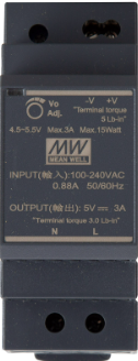
The Mean Well HDR-30-5 is a 30W, 5V, single-output DIN rail power supply designed for industrial and automation applications. Its compact design and high efficiency make it ideal for use in space-constrained environments. The HDR-30-5 is equipped with built-in protections, including short circuit, overload, and overvoltage protection, ensuring reliable operation in demanding conditions.

Explore Projects Built with Mean Well HDR-30-5

Use Cirkit Designer to design, explore, and prototype these projects online. Some projects support real-time simulation. Click "Open Project" to start designing instantly!
Arduino-Controlled Light-Sensitive LED Circuit
Image of Measuring Brightness with Arduino UNO and LDR: A project utilizing Mean Well HDR-30-5 in a practical application
This circuit is designed to measure ambient light levels using a photocell (LDR) and adjust the brightness of an LED accordingly. The photocell and a 10kΩ resistor form a voltage divider connected to the Arduino's analog input A0, while the LED is driven by digital pin D11 through a 220Ω current-limiting resistor. The Arduino's firmware reads the light level, inverses the value to increase LED brightness as it gets darker, and outputs a corresponding PWM signal to control the LED intensity.
Cirkit Designer LogoOpen Project in Cirkit Designer
ESP32C3 Supermini-Based Smart Environment Monitor and Lighting Control System
Image of Bedside RGB and Lamp: A project utilizing Mean Well HDR-30-5 in a practical application
This is a smart control system featuring an ESP32C3 Supermini microcontroller for interfacing with various sensors and actuators. It includes temperature and humidity sensing, RGB LED strip control, user input via a pushbutton and rotary encoder, and AC power control through a two-channel relay. The system is powered by an AC source converted to DC by the HLK-PM12 module.
Cirkit Designer LogoOpen Project in Cirkit Designer
Arduino and ESP32-Based Smart Light and Motor Control System with DHT11 Sensor and I2C LCD
Image of automation project: A project utilizing Mean Well HDR-30-5 in a practical application
This circuit is a smart system that uses an Arduino UNO to detect light levels with an LDR sensor, control an LED and a motor based on the light detected, and measure temperature and humidity with a DHT11 sensor. The data is displayed on an I2C LCD and sent to an IoT system via an ESP32, allowing remote monitoring and control of the motor.
Cirkit Designer LogoOpen Project in Cirkit Designer
Arduino UNO Light-Activated Alarm with KY-018 LDR and Loudspeaker
Image of LASER RX: A project utilizing Mean Well HDR-30-5 in a practical application
This circuit uses an Arduino UNO to read light intensity from a KY-018 LDR Photo Resistor and control a loudspeaker. The LDR is powered by the Arduino's 5V and GND pins, with its signal pin connected to digital pin D0, while the loudspeaker is connected to digital pin D11 and GND.
Cirkit Designer LogoOpen Project in Cirkit Designer

Explore Projects Built with Mean Well HDR-30-5

Use Cirkit Designer to design, explore, and prototype these projects online. Some projects support real-time simulation. Click "Open Project" to start designing instantly!
Image of Measuring Brightness with Arduino UNO and LDR: A project utilizing Mean Well HDR-30-5 in a practical application
Arduino-Controlled Light-Sensitive LED Circuit
This circuit is designed to measure ambient light levels using a photocell (LDR) and adjust the brightness of an LED accordingly. The photocell and a 10kΩ resistor form a voltage divider connected to the Arduino's analog input A0, while the LED is driven by digital pin D11 through a 220Ω current-limiting resistor. The Arduino's firmware reads the light level, inverses the value to increase LED brightness as it gets darker, and outputs a corresponding PWM signal to control the LED intensity.
Cirkit Designer LogoOpen Project in Cirkit Designer
Image of Bedside RGB and Lamp: A project utilizing Mean Well HDR-30-5 in a practical application
ESP32C3 Supermini-Based Smart Environment Monitor and Lighting Control System
This is a smart control system featuring an ESP32C3 Supermini microcontroller for interfacing with various sensors and actuators. It includes temperature and humidity sensing, RGB LED strip control, user input via a pushbutton and rotary encoder, and AC power control through a two-channel relay. The system is powered by an AC source converted to DC by the HLK-PM12 module.
Cirkit Designer LogoOpen Project in Cirkit Designer
Image of automation project: A project utilizing Mean Well HDR-30-5 in a practical application
Arduino and ESP32-Based Smart Light and Motor Control System with DHT11 Sensor and I2C LCD
This circuit is a smart system that uses an Arduino UNO to detect light levels with an LDR sensor, control an LED and a motor based on the light detected, and measure temperature and humidity with a DHT11 sensor. The data is displayed on an I2C LCD and sent to an IoT system via an ESP32, allowing remote monitoring and control of the motor.
Cirkit Designer LogoOpen Project in Cirkit Designer
Image of LASER RX: A project utilizing Mean Well HDR-30-5 in a practical application
Arduino UNO Light-Activated Alarm with KY-018 LDR and Loudspeaker
This circuit uses an Arduino UNO to read light intensity from a KY-018 LDR Photo Resistor and control a loudspeaker. The LDR is powered by the Arduino's 5V and GND pins, with its signal pin connected to digital pin D0, while the loudspeaker is connected to digital pin D11 and GND.
Cirkit Designer LogoOpen Project in Cirkit Designer

Common Applications and Use Cases

  • Industrial control systems
  • Building automation
  • Factory automation equipment
  • IoT devices and sensors
  • LED lighting systems
  • Security and surveillance systems

Technical Specifications

The following table outlines the key technical specifications of the Mean Well HDR-30-5:

Parameter Value
Output Voltage 5V DC
Output Current 0 ~ 4.5A
Output Power 30W
Input Voltage Range 85 ~ 264VAC / 120 ~ 370VDC
Efficiency Up to 85%
Operating Temperature -30°C to +70°C
Dimensions 90 x 54 x 54 mm (H x W x D)
Mounting Type DIN rail (TS-35/7.5 or TS-35/15)
Protections Short circuit, overload, overvoltage
Certifications UL, CE, EAC, CB, RoHS

Pin Configuration and Descriptions

The HDR-30-5 features screw terminal connections for input and output. The pin configuration is as follows:

Pin Label Description
1 L AC Line Input
2 N AC Neutral Input
3 -V DC Output Negative (-)
4 +V DC Output Positive (+)

Usage Instructions

How to Use the HDR-30-5 in a Circuit

  1. Mounting: Securely mount the HDR-30-5 on a DIN rail (TS-35/7.5 or TS-35/15).
  2. Input Connection:
    • Connect the AC line (L) and neutral (N) wires to the input terminals.
    • Ensure the input voltage is within the specified range (85 ~ 264VAC).
  3. Output Connection:
    • Connect the load to the +V and -V output terminals.
    • Verify that the load does not exceed the maximum output current (4.5A).
  4. Power On:
    • After verifying all connections, power on the AC supply.
    • The HDR-30-5 will provide a stable 5V DC output to the connected load.

Important Considerations and Best Practices

  • Ventilation: Ensure adequate ventilation around the power supply to prevent overheating.
  • Load Requirements: Do not exceed the maximum output power of 30W to avoid triggering overload protection.
  • Wiring: Use appropriately rated wires for both input and output connections.
  • Grounding: Proper grounding is recommended to ensure safety and reduce electrical noise.
  • Testing: Before connecting sensitive devices, test the output voltage with a multimeter to confirm proper operation.

Example: Connecting to an Arduino UNO

The HDR-30-5 can be used to power an Arduino UNO. Follow these steps:

  1. Connect the +V terminal of the HDR-30-5 to the Arduino's 5V pin.
  2. Connect the -V terminal of the HDR-30-5 to the Arduino's GND pin.
  3. Ensure the HDR-30-5 is powered on and providing a stable 5V output.

Here is an example Arduino sketch to blink an LED when powered by the HDR-30-5:

// Blink an LED connected to pin 13
// Ensure the Arduino is powered by the HDR-30-5 (5V DC)

void setup() {
  pinMode(13, OUTPUT); // Set pin 13 as an output
}

void loop() {
  digitalWrite(13, HIGH); // Turn the LED on
  delay(1000);            // Wait for 1 second
  digitalWrite(13, LOW);  // Turn the LED off
  delay(1000);            // Wait for 1 second
}

Troubleshooting and FAQs

Common Issues and Solutions

  1. No Output Voltage:

    • Cause: Input voltage is not within the specified range.
    • Solution: Verify the AC input voltage and ensure proper wiring.
  2. Overload Protection Triggered:

    • Cause: Load exceeds the maximum output power (30W).
    • Solution: Reduce the load to within the specified limits.
  3. Overheating:

    • Cause: Insufficient ventilation or operation in high-temperature environments.
    • Solution: Improve airflow around the power supply or operate within the recommended temperature range.
  4. Intermittent Output:

    • Cause: Loose connections or fluctuating input voltage.
    • Solution: Check all connections and ensure a stable input voltage.

FAQs

Q1: Can the HDR-30-5 be used outdoors?
A1: No, the HDR-30-5 is not weatherproof and should only be used in indoor environments or within a protective enclosure.

Q2: What happens if the load exceeds 4.5A?
A2: The HDR-30-5 will activate overload protection, shutting down the output to protect the device and connected equipment.

Q3: Can I use the HDR-30-5 with DC input?
A3: Yes, the HDR-30-5 supports a DC input range of 120 ~ 370VDC.

Q4: Is the HDR-30-5 suitable for sensitive electronics?
A4: Yes, the HDR-30-5 provides a stable 5V DC output, making it suitable for powering sensitive electronics like microcontrollers and sensors.