How to Use ELRS Receiver: Examples, Pinouts, and Specs
Introduction
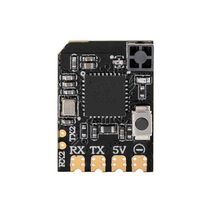
The ELRS Receiver (RP2), manufactured by RadioMaster, is a high-performance, long-range radio receiver designed for remote control applications. It is part of the ExpressLRS ecosystem, which is renowned for its low latency, high reliability, and exceptional range. The RP2 receiver is particularly well-suited for drones, RC vehicles, and other applications requiring precise and responsive control.
Common use cases include:
- FPV (First-Person View) drones: Ideal for competitive racing and freestyle flying.
- RC vehicles: Provides reliable control for cars, boats, and other remote-controlled models.
- Long-range applications: Ensures stable communication over extended distances.
Explore Projects Built with ELRS Receiver


Explore Projects Built with ELRS Receiver
Technical Specifications
The following are the key technical details of the RadioMaster RP2 ELRS Receiver:
| Parameter | Specification |
|---|---|
| Manufacturer | RadioMaster |
| Model | RP2 |
| Protocol | ExpressLRS (ELRS) |
| Frequency Range | 2.4 GHz or 900 MHz (depending on variant) |
| Input Voltage | 5V (via external power source) |
| Antenna Type | External, IPEX connector |
| Latency | Ultra-low (as low as 4 ms) |
| Range | Up to 30 km (depending on environment) |
| Dimensions | 10 mm x 15 mm x 3 mm |
| Weight | 1.5 g |
| Firmware Compatibility | ExpressLRS firmware (open-source) |
Pin Configuration and Descriptions
The RP2 receiver has a simple pinout for easy integration into your projects. Below is the pin configuration:
| Pin | Name | Description |
|---|---|---|
| 1 | GND | Ground connection |
| 2 | 5V | Power input (5V) |
| 3 | TX | UART Transmit (to flight controller RX pin) |
| 4 | RX | UART Receive (to flight controller TX pin) |
Usage Instructions
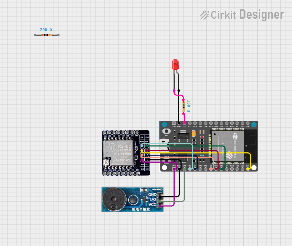
How to Use the RP2 ELRS Receiver in a Circuit
Wiring the Receiver:
- Connect the GND pin to the ground of your flight controller or power source.
- Connect the 5V pin to a 5V power source.
- Connect the TX pin of the receiver to the RX pin of your flight controller.
- Connect the RX pin of the receiver to the TX pin of your flight controller.
Binding the Receiver:
- Power on the receiver and transmitter module.
- Put the transmitter module into binding mode (refer to your transmitter's manual).
- The receiver will automatically bind to the transmitter. A solid LED indicates a successful bind.
Configuring the Receiver:
- Use the ExpressLRS Configurator tool to flash the appropriate firmware to the receiver.
- Ensure the firmware version matches the transmitter module for compatibility.
Testing the Connection:
- Verify the receiver is communicating with the transmitter by checking the signal strength (RSSI) and control responsiveness.
Important Considerations and Best Practices
- Antenna Placement: Ensure the antenna is positioned away from metal components or other electronics to avoid signal interference.
- Firmware Updates: Regularly update the receiver firmware using the ExpressLRS Configurator to benefit from the latest features and improvements.
- Power Supply: Use a stable 5V power source to prevent brownouts or signal loss.
- UART Configuration: Configure the UART port on your flight controller to match the receiver's settings (e.g., baud rate).
Example Code for Arduino UNO
While the RP2 receiver is typically used with flight controllers, it can also be connected to an Arduino UNO for testing or custom applications. Below is an example code snippet to read data from the receiver:
#include <SoftwareSerial.h>

// Define RX and TX pins for the Arduino
#define RX_PIN 10  // Connect to RP2 TX pin
#define TX_PIN 11  // Connect to RP2 RX pin

// Initialize SoftwareSerial for communication with the receiver
SoftwareSerial elrsSerial(RX_PIN, TX_PIN);

void setup() {
  // Start serial communication with the receiver
  elrsSerial.begin(115200); // Ensure baud rate matches receiver settings
  Serial.begin(9600);       // For debugging via Serial Monitor

  Serial.println("ELRS Receiver Test Initialized");
}

void loop() {
  // Check if data is available from the receiver
  if (elrsSerial.available()) {
    // Read and print the received data
    char receivedData = elrsSerial.read();
    Serial.print("Received: ");
    Serial.println(receivedData);
  }
}
Note: Ensure the baud rate in the code matches the receiver's configuration. This example is for testing purposes and may require additional logic for specific applications.
Troubleshooting and FAQs
Common Issues and Solutions
Receiver Not Binding to Transmitter:
- Ensure the receiver and transmitter are on the same firmware version.
- Verify the transmitter is in binding mode.
- Check the antenna connection for proper installation.
No Signal or Poor Range:
- Ensure the antenna is securely connected and properly positioned.
- Avoid placing the receiver near sources of interference (e.g., ESCs, motors).
- Check for firmware updates to resolve potential bugs.
Receiver Not Powering On:
- Verify the 5V power supply is stable and connected correctly.
- Check for loose or damaged wires.
UART Communication Issues:
- Ensure the TX and RX pins are correctly connected (crossed).
- Verify the UART port settings on the flight controller or Arduino.
FAQs
Q: Can the RP2 receiver be used with any transmitter?
A: The RP2 is compatible with any transmitter running ExpressLRS firmware. Ensure the firmware versions match for proper operation.
Q: What is the maximum range of the RP2 receiver?
A: The range can reach up to 30 km in optimal conditions, but this depends on the environment and antenna placement.
Q: How do I update the firmware on the RP2 receiver?
A: Use the ExpressLRS Configurator tool to flash the latest firmware via USB or Wi-Fi (if supported).
Q: Can I use the RP2 receiver with a 3.3V power source?
A: No, the RP2 requires a 5V power source for proper operation.
By following this documentation, you can effectively integrate and troubleshoot the RadioMaster RP2 ELRS Receiver in your projects.