How to Use Color Module: Examples, Pinouts, and Specs
Introduction
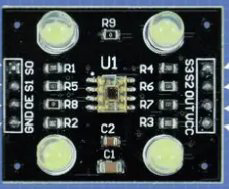
A Color Module is a versatile electronic component designed for the control and manipulation of colors in various applications. It typically features RGB (Red, Green, Blue) LEDs or similar elements, enabling the creation of a wide spectrum of colors by adjusting the intensity of each color channel. This module is widely used in electronic displays, decorative lighting systems, and projects requiring dynamic color effects.
Explore Projects Built with Color Module
Explore Projects Built with Color Module
Common Applications and Use Cases
- RGB LED displays and signage
- Ambient lighting systems
- Smart home lighting solutions
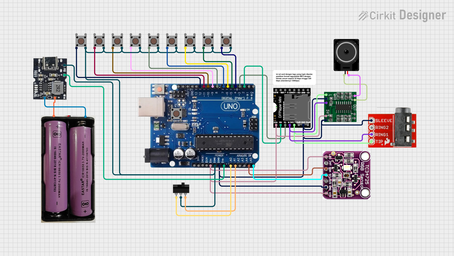
- Robotics and interactive projects
- Educational projects for learning about color mixing and light control
Technical Specifications
Below are the key technical details of a typical Color Module:
| Parameter | Value |
|---|---|
| Operating Voltage | 3.3V to 5V |
| Operating Current | 20mA per channel (typical) |
| LED Type | RGB LED (common cathode or anode) |
| Control Method | PWM (Pulse Width Modulation) |
| Dimensions | Varies by model (e.g., 25mm x 25mm) |
| Interface | 3-pin or 4-pin (VCC, GND, R, G, B) |
Pin Configuration and Descriptions
The pinout of a standard 4-pin RGB Color Module is as follows:
| Pin | Name | Description |
|---|---|---|
| 1 | VCC | Power supply input (3.3V or 5V) |
| 2 | GND | Ground connection |
| 3 | R | Red channel control (PWM input) |
| 4 | G | Green channel control (PWM input) |
| 5 | B | Blue channel control (PWM input) |
Note: Some modules may use a common cathode or common anode configuration. Ensure compatibility with your circuit.
Usage Instructions
How to Use the Color Module in a Circuit
- Power the Module: Connect the VCC pin to a 3.3V or 5V power source and the GND pin to the ground.
- Control the Colors: Use PWM signals on the R, G, and B pins to control the intensity of each color channel. The combination of these signals determines the final color output.
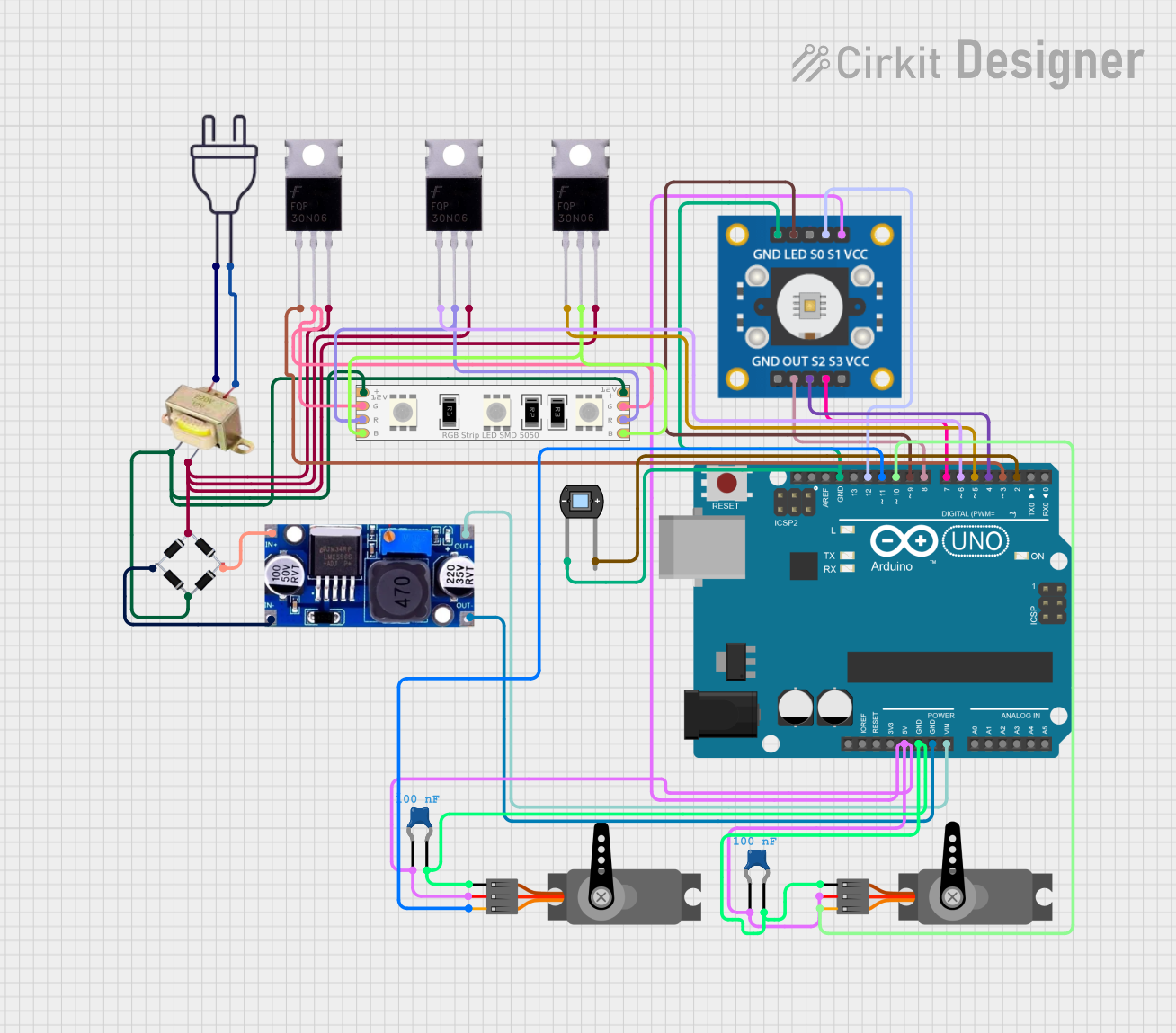
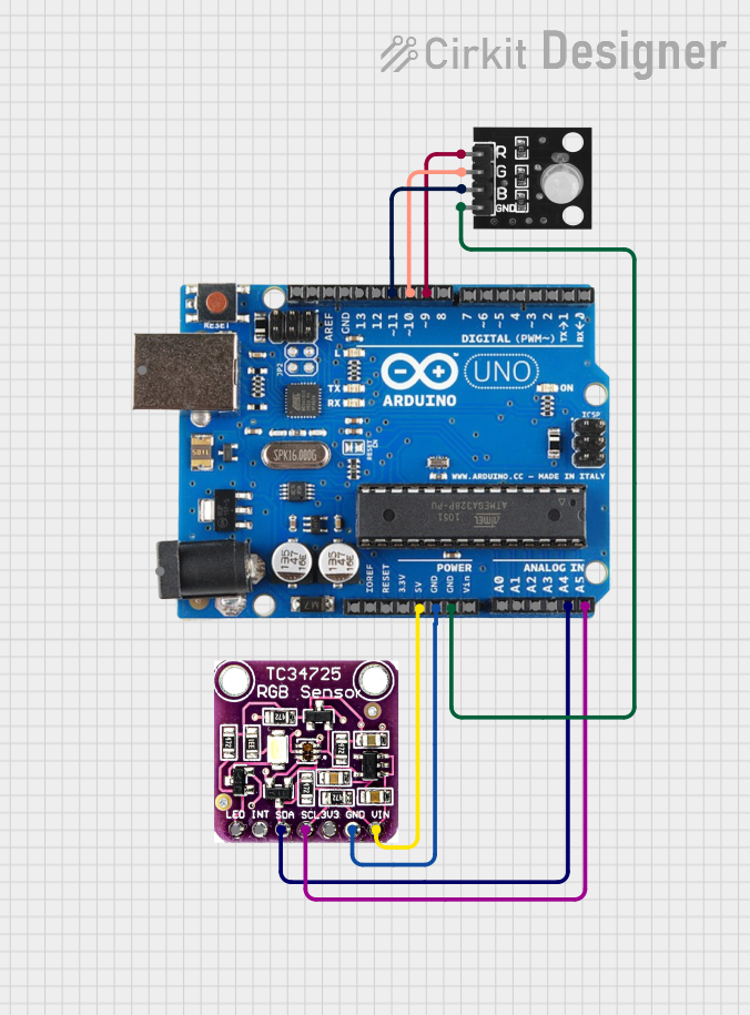
- Connect to a Microcontroller: The module can be connected to a microcontroller (e.g., Arduino UNO) for precise color control.
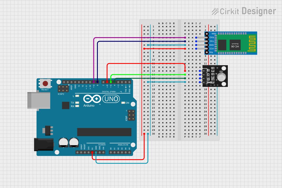
Example Circuit with Arduino UNO
Below is an example of how to connect and control a Color Module using an Arduino UNO:
Circuit Connections
- Connect the VCC pin of the Color Module to the 5V pin on the Arduino.
- Connect the GND pin of the Color Module to the GND pin on the Arduino.
- Connect the R, G, and B pins of the Color Module to PWM-capable pins on the Arduino (e.g., pins 9, 10, and 11).
Example Code
// Define the pins for the RGB channels
const int redPin = 9;   // Red channel connected to pin 9
const int greenPin = 10; // Green channel connected to pin 10
const int bluePin = 11;  // Blue channel connected to pin 11

void setup() {
  // Set the RGB pins as output
  pinMode(redPin, OUTPUT);
  pinMode(greenPin, OUTPUT);
  pinMode(bluePin, OUTPUT);
}

void loop() {
  // Example: Cycle through colors
  setColor(255, 0, 0);  // Red
  delay(1000);          // Wait 1 second
  setColor(0, 255, 0);  // Green
  delay(1000);          // Wait 1 second
  setColor(0, 0, 255);  // Blue
  delay(1000);          // Wait 1 second
  setColor(255, 255, 0); // Yellow
  delay(1000);          // Wait 1 second
}

// Function to set the color by adjusting PWM values
void setColor(int red, int green, int blue) {
  analogWrite(redPin, red);   // Set red intensity
  analogWrite(greenPin, green); // Set green intensity
  analogWrite(bluePin, blue);  // Set blue intensity
}
Important Considerations and Best Practices
- Power Supply: Ensure the power supply voltage matches the module's requirements (3.3V or 5V).
- PWM Frequency: Use a PWM frequency that is compatible with the module to avoid flickering.
- Resistors: Some modules may require current-limiting resistors for each channel. Check the datasheet or module documentation.
- Heat Management: Prolonged use at high intensities may generate heat. Ensure proper ventilation.
Troubleshooting and FAQs
Common Issues and Solutions
No Light Output:
- Verify the power supply connections (VCC and GND).
- Check the PWM signal connections to the R, G, and B pins.
- Ensure the module is not damaged.
Incorrect Colors:
- Verify the PWM values being sent to each channel.
- Check for swapped connections between the R, G, and B pins.
Flickering:
- Ensure the PWM frequency is high enough to avoid visible flicker.
- Check for loose connections or unstable power supply.
Overheating:
- Reduce the intensity of the LEDs by lowering the PWM duty cycle.
- Ensure proper ventilation around the module.
FAQs
Q: Can I use the Color Module with a 12V power supply?
A: No, most Color Modules are designed for 3.3V or 5V operation. Using a higher voltage may damage the module.
Q: How do I create custom colors?
A: By varying the PWM duty cycle for each channel (R, G, B), you can mix colors to create custom shades.
Q: Can I control the module without a microcontroller?
A: Yes, you can use potentiometers or other analog control methods to adjust the intensity of each channel manually.
Q: Is the module compatible with other microcontrollers?
A: Yes, the module can be used with any microcontroller that supports PWM output, such as ESP32, Raspberry Pi, or STM32.
By following this documentation, you can effectively integrate and use a Color Module in your projects!