How to Use CD4017: Examples, Pinouts, and Specs
Introduction
The CD4017 is a decade counter IC manufactured by Onsemi with the part ID CD4017BCN. It is a versatile CMOS-based integrated circuit that counts from 0 to 10 and provides ten output signals, each corresponding to a count. The IC is widely used in applications such as LED chasers, frequency dividers, and sequential timing circuits. Its ability to sequentially activate outputs makes it ideal for projects requiring step-by-step control.
Explore Projects Built with CD4017

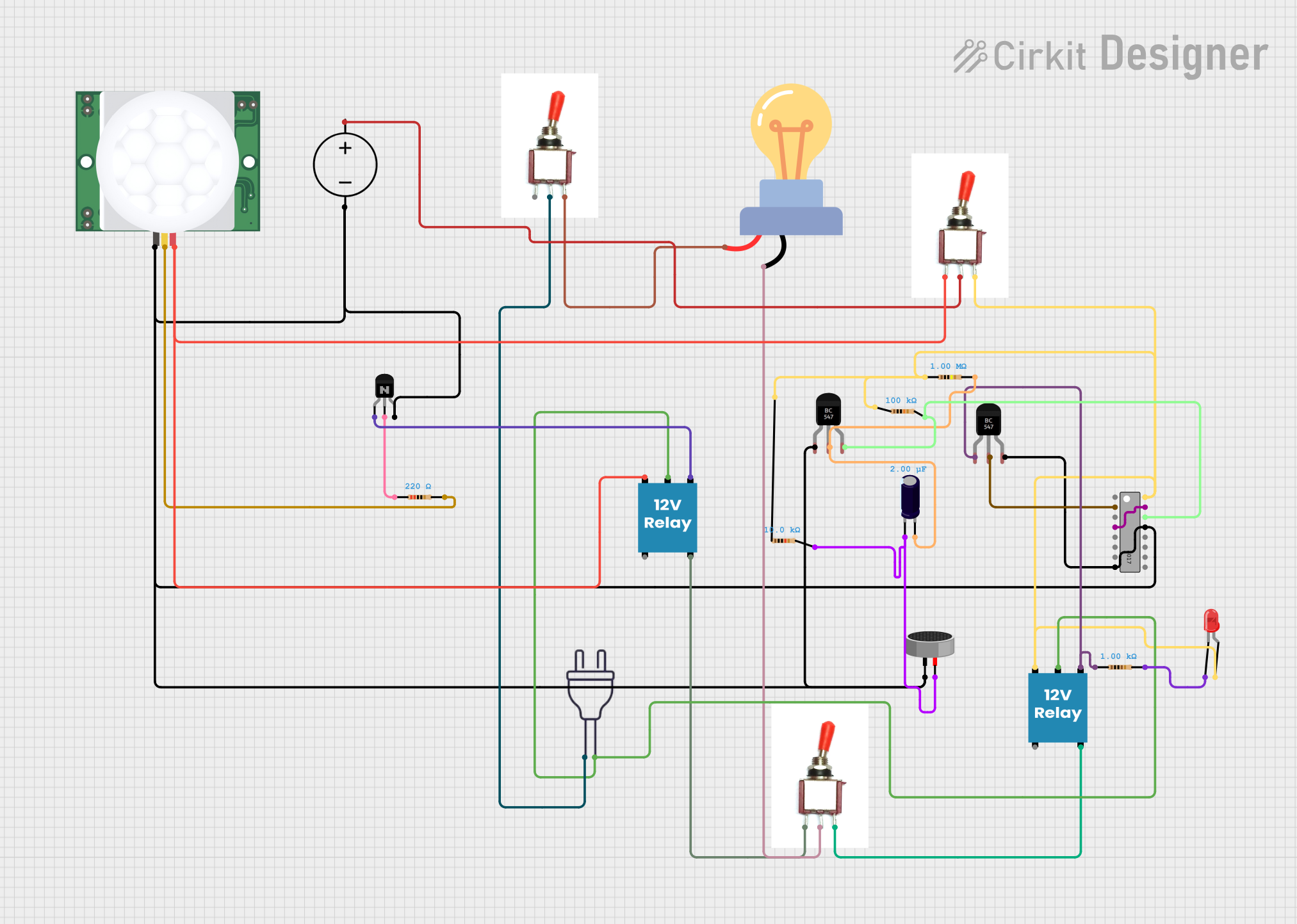
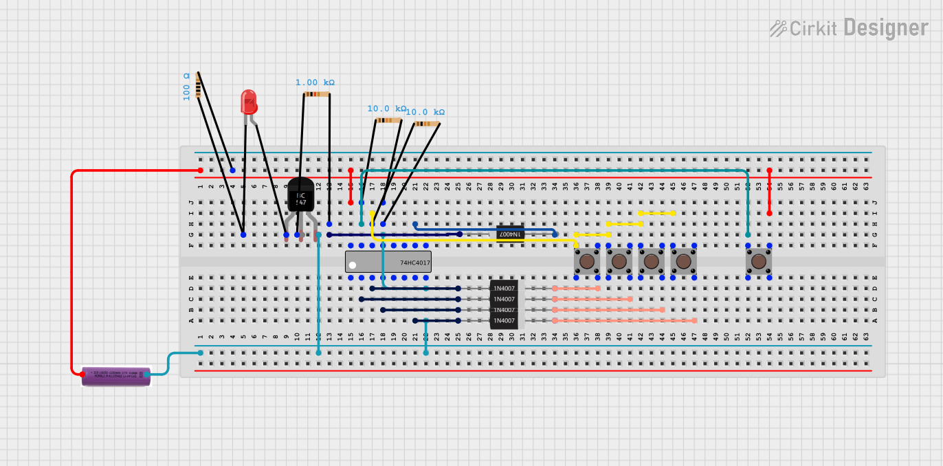
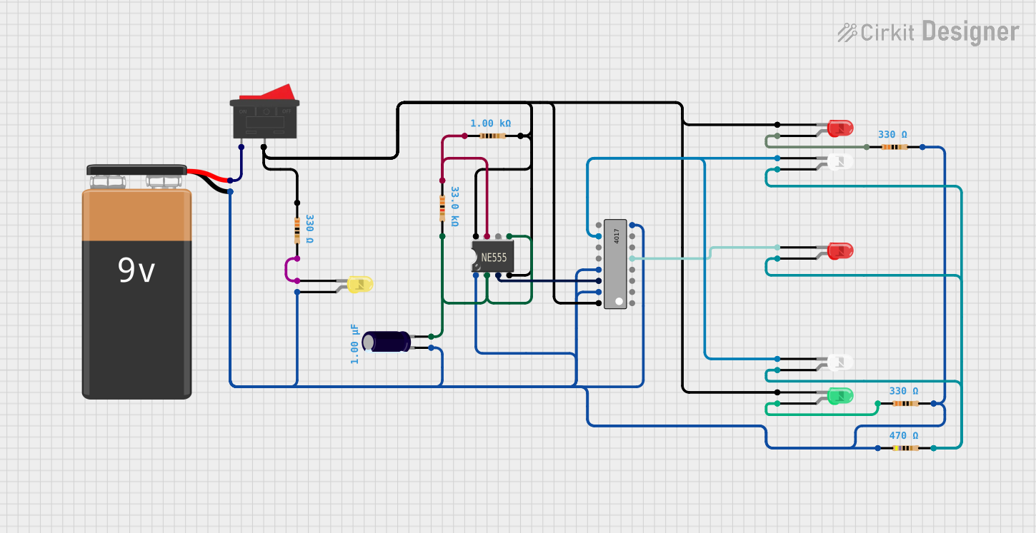
Explore Projects Built with CD4017
Common Applications
- LED chasers and sequencers
- Frequency division circuits
- Digital clocks
- Event counters
- Light animations and displays
Technical Specifications
The CD4017 is a robust IC with the following key specifications:
| Parameter | Value |
|---|---|
| Supply Voltage (V(_{DD})) | 3V to 15V |
| Maximum Clock Frequency | 5 MHz (at 10V supply) |
| Output Current (I(_{OH})) | -1.5 mA (typical) |
| Output Current (I(_{OL})) | 1.5 mA (typical) |
| Power Dissipation | 500 mW |
| Operating Temperature Range | -55°C to +125°C |
| Package Type | 16-PDIP (Through-hole plastic) |
Pin Configuration and Descriptions
The CD4017 has 16 pins, each serving a specific function. The pinout is as follows:
| Pin Number | Pin Name | Description |
|---|---|---|
| 1 | Q0 | Output 0 (first output in the sequence) |
| 2 | Q1 | Output 1 |
| 3 | Q2 | Output 2 |
| 4 | Q3 | Output 3 |
| 5 | Q4 | Output 4 |
| 6 | Q5 | Output 5 |
| 7 | Q6 | Output 6 |
| 8 | GND | Ground (0V reference) |
| 9 | Q7 | Output 7 |
| 10 | Q8 | Output 8 |
| 11 | Q9 | Output 9 (last output in the sequence) |
| 12 | Carry Out | Outputs a pulse after every 10 clock pulses (used for cascading multiple ICs) |
| 13 | Clock Enable | Enables or disables the clock input (active LOW) |
| 14 | Clock | Clock input signal (triggers the counter) |
| 15 | Reset | Resets the counter to 0 (active HIGH) |
| 16 | V(_{DD}) | Positive supply voltage |
Usage Instructions
The CD4017 is straightforward to use in a circuit. Below are the steps and considerations for proper usage:
Basic Circuit Setup
- Power Supply: Connect pin 16 (V(_{DD})) to the positive supply voltage (3V to 15V) and pin 8 (GND) to ground.
- Clock Input: Provide a clock signal to pin 14 (Clock). This can be generated using a 555 timer IC, an Arduino, or any other clock source.
- Outputs: Connect the desired outputs (Q0 to Q9) to your load (e.g., LEDs with current-limiting resistors).
- Reset: If a reset function is required, connect pin 15 (Reset) to a control signal. Otherwise, tie it to GND to disable the reset function.
- Clock Enable: Tie pin 13 (Clock Enable) to GND to enable the clock. If you want to disable the clock, connect it to V(_{DD}).
Example: LED Chaser Circuit with Arduino UNO
The following example demonstrates how to use the CD4017 with an Arduino UNO to create an LED chaser:
Circuit Connections
- Connect pin 16 (V(_{DD})) to the Arduino's 5V pin.
- Connect pin 8 (GND) to the Arduino's GND.
- Connect pin 14 (Clock) to Arduino digital pin 2.
- Connect pin 15 (Reset) to GND.
- Connect pin 13 (Clock Enable) to GND.
- Connect LEDs to outputs Q0 to Q9 (pins 1 to 11, excluding pin 8) with 220-ohm resistors in series.
Arduino Code
// CD4017 LED Chaser Example
// Connect CD4017 Clock to Arduino pin 2
// Connect LEDs to CD4017 outputs Q0 to Q9 with 220-ohm resistors

#define CLOCK_PIN 2  // Arduino pin connected to CD4017 Clock (pin 14)
#define DELAY_TIME 200  // Delay time in milliseconds

void setup() {
  pinMode(CLOCK_PIN, OUTPUT);  // Set CLOCK_PIN as output
  digitalWrite(CLOCK_PIN, LOW);  // Initialize clock signal to LOW
}

void loop() {
  // Generate 10 clock pulses to cycle through all outputs
  for (int i = 0; i < 10; i++) {
    digitalWrite(CLOCK_PIN, HIGH);  // Set clock HIGH
    delay(DELAY_TIME);  // Wait for DELAY_TIME
    digitalWrite(CLOCK_PIN, LOW);  // Set clock LOW
    delay(DELAY_TIME);  // Wait for DELAY_TIME
  }
}
Best Practices
- Use decoupling capacitors (e.g., 0.1 µF) across the power supply pins (V(_{DD}) and GND) to reduce noise.
- Avoid exceeding the maximum voltage and current ratings to prevent damage to the IC.
- If cascading multiple CD4017 ICs, connect the Carry Out pin (pin 12) of the first IC to the Clock input (pin 14) of the next IC.
Troubleshooting and FAQs
Common Issues and Solutions
Outputs Not Changing:
- Ensure the clock signal is properly connected and functioning.
- Verify that the Clock Enable pin (pin 13) is tied to GND.
- Check the Reset pin (pin 15) to ensure it is not unintentionally HIGH.
LEDs Not Lighting Up:
- Confirm that the LEDs are connected with the correct polarity.
- Use appropriate current-limiting resistors to prevent overloading the outputs.
IC Overheating:
- Check for excessive supply voltage or current draw.
- Ensure proper decoupling capacitors are used to stabilize the power supply.
FAQs
Q1: Can I use the CD4017 with a 3.3V microcontroller?
A1: Yes, the CD4017 operates with supply voltages as low as 3V. Ensure the clock signal voltage matches the IC's supply voltage.
Q2: How do I cascade multiple CD4017 ICs?
A2: Connect the Carry Out pin (pin 12) of the first IC to the Clock input (pin 14) of the next IC. This allows the second IC to count after the first IC completes its cycle.
Q3: What is the maximum clock frequency for the CD4017?
A3: The maximum clock frequency is 5 MHz when operating at a 10V supply. For lower supply voltages, the maximum frequency decreases.
By following this documentation, you can effectively integrate the CD4017 into your projects and troubleshoot common issues with ease.