How to Use 1.54'' TFT Display 240x240 spi ST7789: Examples, Pinouts, and Specs
Introduction
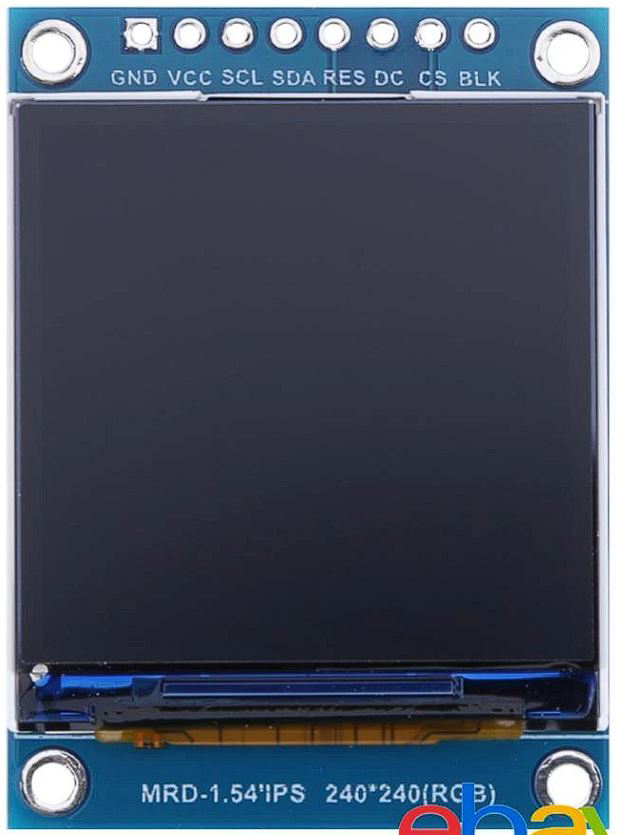
The 1.54-inch TFT display is a compact, high-resolution screen with a resolution of 240x240 pixels. It uses the ST7789 driver and communicates via the SPI (Serial Peripheral Interface) protocol. This display is ideal for applications requiring a vibrant and colorful interface in a small form factor, such as smartwatches, IoT devices, handheld instruments, and embedded systems.
Explore Projects Built with 1.54'' TFT Display 240x240 spi ST7789


Explore Projects Built with 1.54'' TFT Display 240x240 spi ST7789
Common Applications and Use Cases
- Smartwatches and wearable devices
- IoT dashboards and status displays
- Portable gaming consoles
- Industrial control panels
- DIY electronics projects with microcontrollers (e.g., Arduino, Raspberry Pi)
Technical Specifications
Key Technical Details
| Parameter | Value |
|---|---|
| Display Type | TFT (Thin-Film Transistor) |
| Resolution | 240x240 pixels |
| Driver IC | ST7789 |
| Communication Protocol | SPI (4-wire) |
| Operating Voltage | 3.3V (logic and backlight) |
| Backlight | LED |
| Display Colors | 65K (16-bit RGB) |
| Viewing Angle | Wide |
| Operating Temperature | -20°C to 70°C |
| Dimensions | 1.54 inches (diagonal) |
Pin Configuration and Descriptions
| Pin Name | Pin Number | Description |
|---|---|---|
| VCC | 1 | Power supply input (3.3V recommended) |
| GND | 2 | Ground connection |
| SCL | 3 | SPI clock line (SCK) |
| SDA | 4 | SPI data line (MOSI) |
| RES | 5 | Reset pin (active low) |
| DC | 6 | Data/Command control pin |
| BLK | 7 | Backlight control (connect to 3.3V for always on) |
Usage Instructions
How to Use the Component in a Circuit
- Power Supply: Connect the
VCCpin to a 3.3V power source and theGNDpin to ground. - SPI Communication: Connect the
SCL(SPI clock) andSDA(SPI data) pins to the corresponding SPI pins on your microcontroller. - Control Pins:
- Connect the
RESpin to a GPIO pin on your microcontroller for resetting the display. - Connect the
DCpin to a GPIO pin to toggle between data and command modes.
- Connect the
- Backlight: Connect the
BLKpin to 3.3V for constant backlight or to a PWM-capable GPIO pin for brightness control.
Important Considerations and Best Practices
- Voltage Levels: Ensure all logic signals are 3.3V. If using a 5V microcontroller (e.g., Arduino UNO), use level shifters to avoid damaging the display.
- SPI Speed: The ST7789 supports high SPI clock speeds, but start with a moderate speed (e.g., 4 MHz) to ensure stable communication.
- Initialization: The display requires specific initialization commands to configure the ST7789 driver. Use a compatible library to simplify this process.
- Backlight Control: Use PWM to adjust the backlight brightness for power savings and better user experience.
Example Code for Arduino UNO
Below is an example of how to use the 1.54'' TFT display with an Arduino UNO using the Adafruit ST7789 library.
#include <Adafruit_GFX.h>    // Core graphics library
#include <Adafruit_ST7789.h> // ST7789 driver library
#include <SPI.h>             // SPI library

// Define pins for the display
#define TFT_CS    10  // Chip select pin (not used, tie to GND)
#define TFT_RST   9   // Reset pin
#define TFT_DC    8   // Data/Command pin

// Create an instance of the display
Adafruit_ST7789 tft = Adafruit_ST7789(TFT_CS, TFT_DC, TFT_RST);

void setup() {
  // Initialize serial communication for debugging
  Serial.begin(9600);
  Serial.println("TFT Display Test");

  // Initialize the display
  tft.init(240, 240); // Initialize with 240x240 resolution
  tft.setRotation(0); // Set display orientation

  // Fill the screen with a color
  tft.fillScreen(ST77XX_BLACK);
  tft.setTextColor(ST77XX_WHITE);
  tft.setTextSize(2);
  tft.setCursor(10, 10);
  tft.println("Hello, World!");
}

void loop() {
  // Add your code here to update the display
}
Notes:
- Install the Adafruit GFX and Adafruit ST7789 libraries via the Arduino Library Manager before running the code.
- Adjust the
TFT_CS,TFT_RST, andTFT_DCpin definitions to match your wiring.
Troubleshooting and FAQs
Common Issues and Solutions
Display Not Turning On:
- Verify the power connections (
VCCandGND). - Ensure the backlight pin (
BLK) is connected to 3.3V or a PWM signal.
- Verify the power connections (
No Output on the Screen:
- Check the SPI connections (
SCLandSDA) and ensure they are correctly wired. - Confirm that the
RESandDCpins are connected to the correct GPIO pins. - Ensure the display initialization code matches the ST7789 driver requirements.
- Check the SPI connections (
Flickering or Unstable Display:
- Reduce the SPI clock speed in your code.
- Check for loose or poor-quality connections.
Incorrect Colors or Artifacts:
- Verify that the display is initialized in 16-bit color mode.
- Ensure the data being sent to the display matches the expected format.
FAQs
Q: Can I use this display with a 5V microcontroller?
A: Yes, but you must use level shifters to convert the 5V logic signals to 3.3V to avoid damaging the display.
Q: How do I control the backlight brightness?
A: Connect the BLK pin to a PWM-capable GPIO pin on your microcontroller and use PWM to adjust the brightness.
Q: Is this display compatible with Raspberry Pi?
A: Yes, the display can be used with Raspberry Pi. Use the SPI interface and configure the ST7789 driver in your software.
Q: Can I daisy-chain multiple displays?
A: No, the ST7789 does not support daisy-chaining. Each display requires a separate SPI connection.