How to Use 4050 Hex Buffer: Examples, Pinouts, and Specs
Introduction
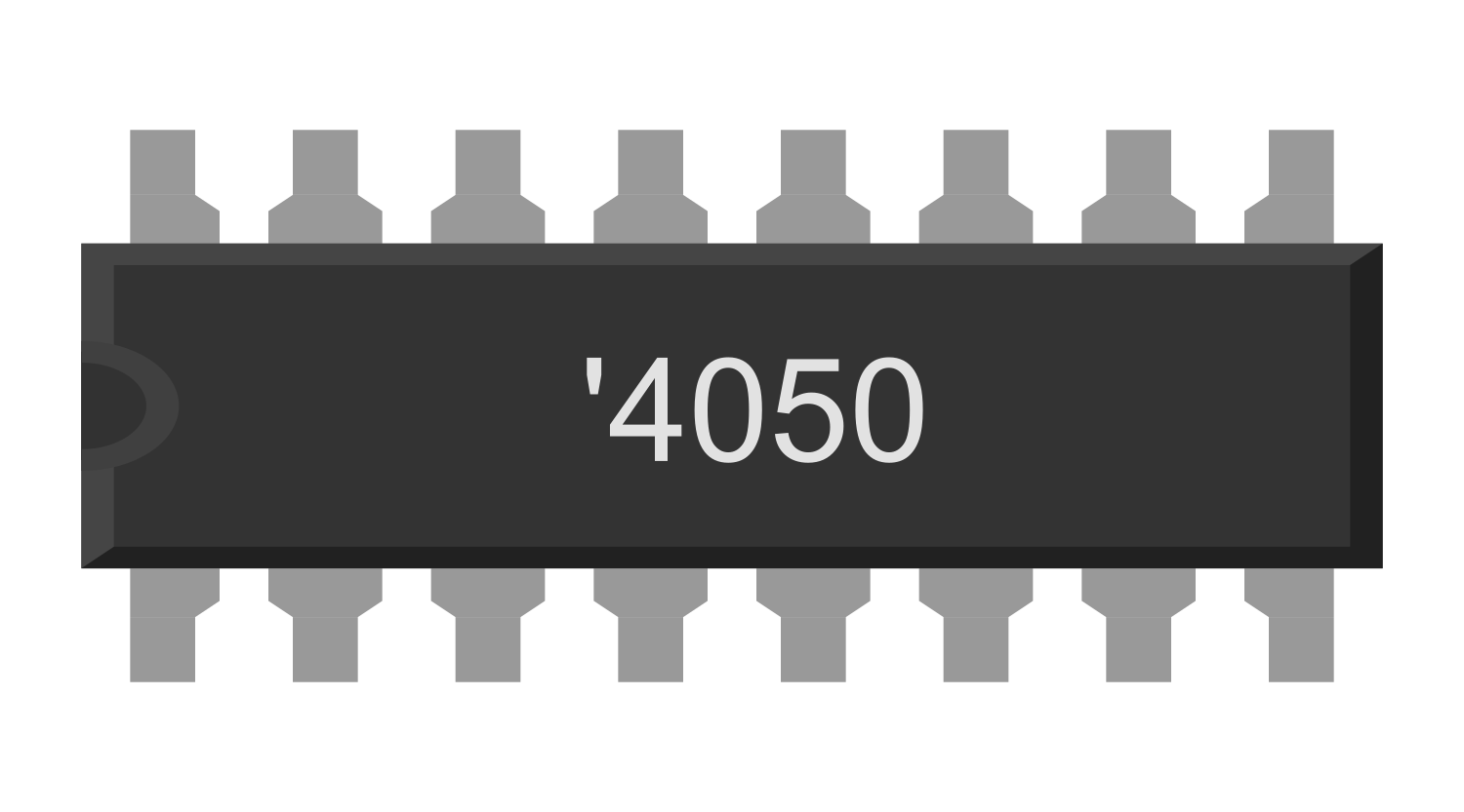
The 4050 Hex Buffer is an integrated circuit (IC) that features six independent non-inverting buffer gates. It is designed to convert high-to-low logic levels, making it particularly useful for interfacing between devices that operate at different voltage levels. The 4050 is often used in digital circuits for buffering and level shifting signals, ensuring signal integrity and preventing distortion or degradation.
Explore Projects Built with 4050 Hex Buffer
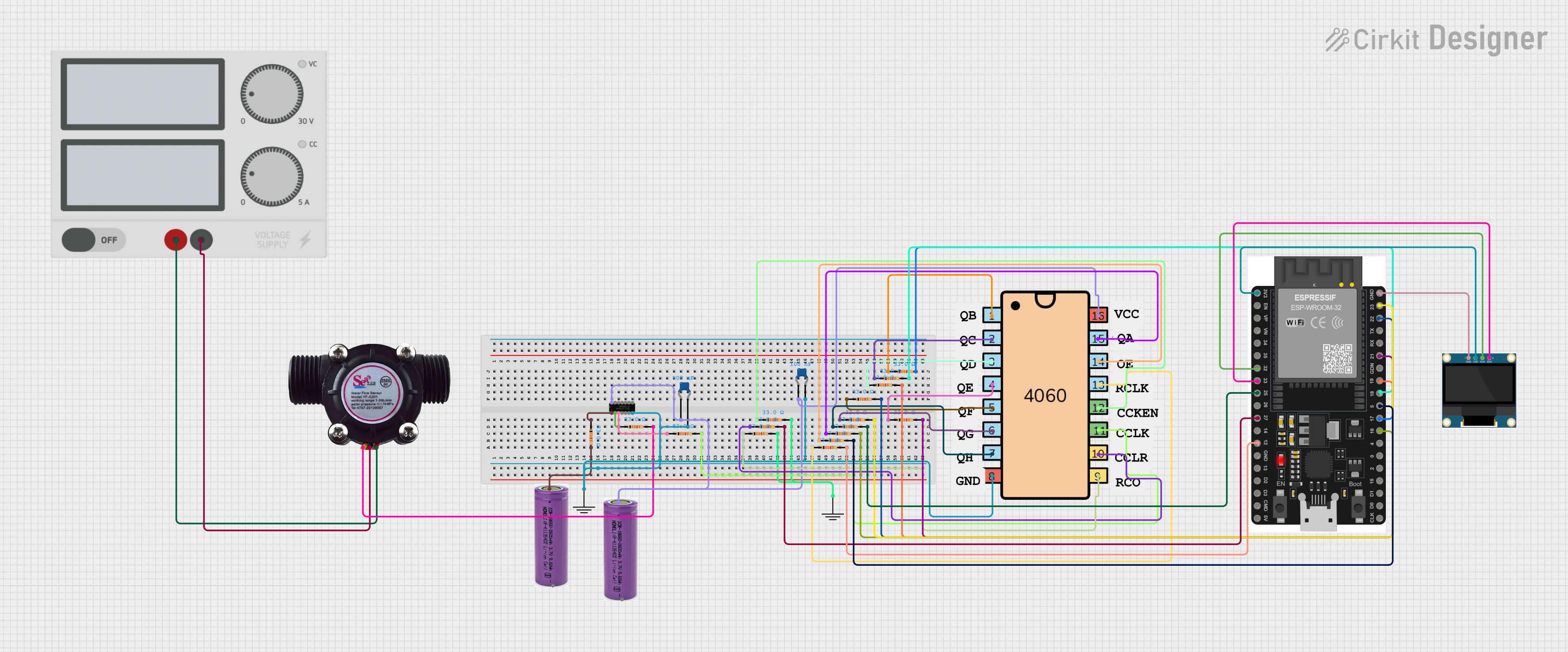
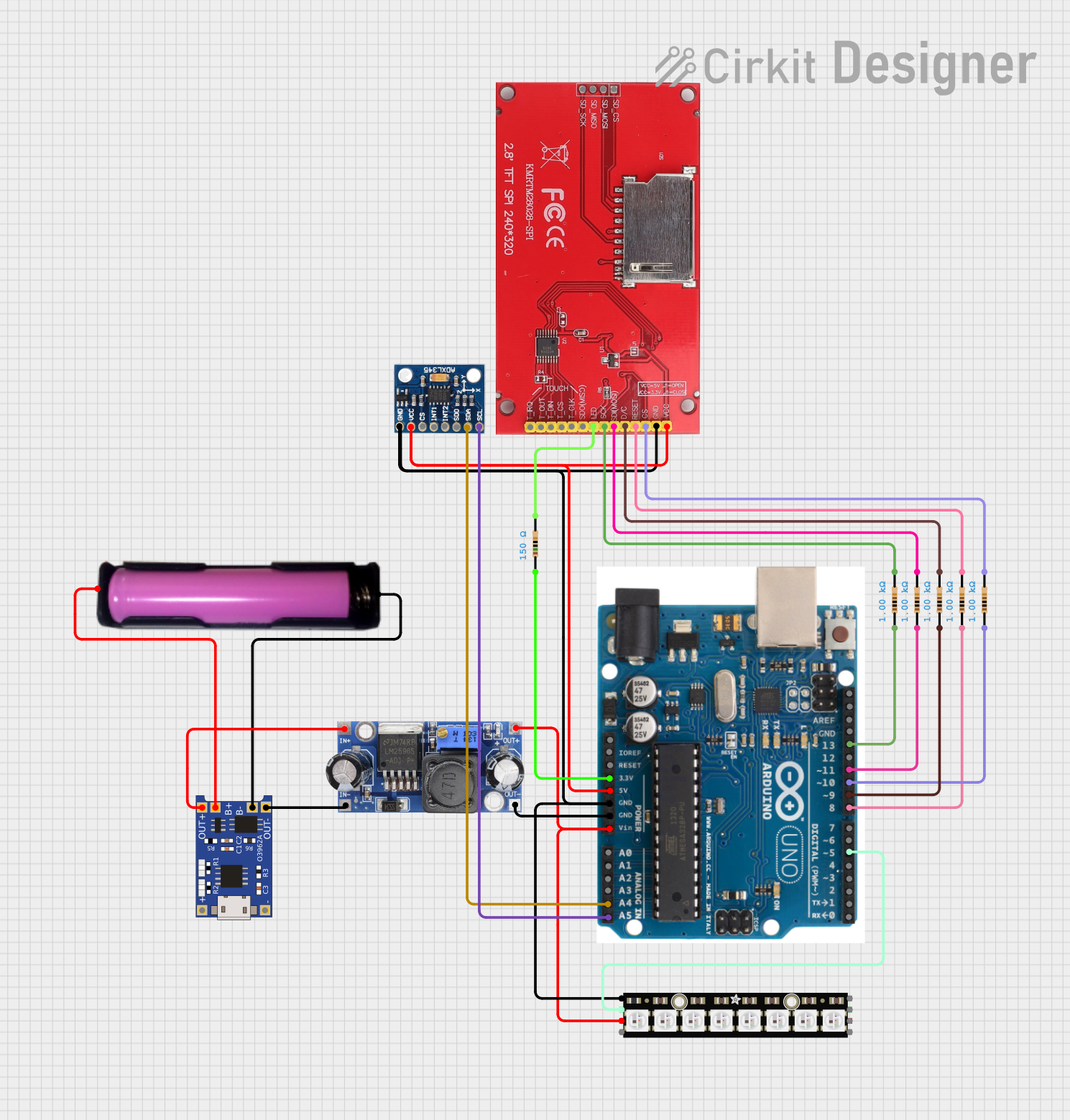
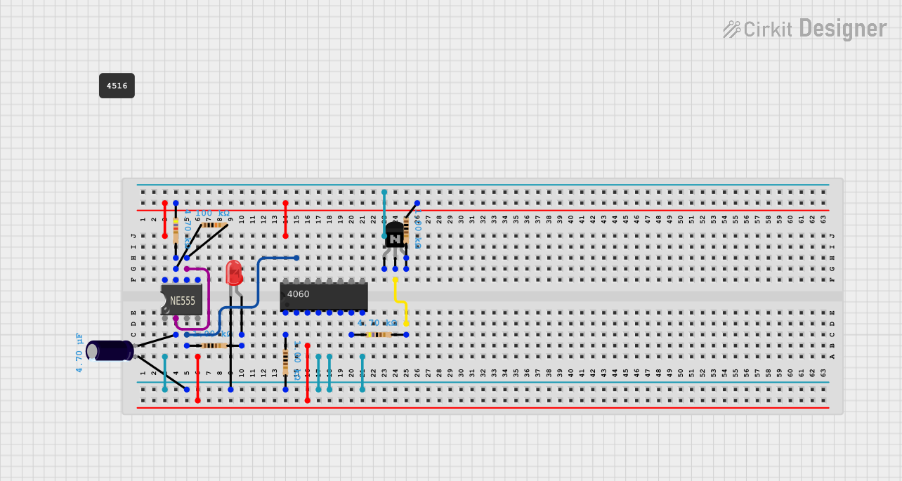

Explore Projects Built with 4050 Hex Buffer
Common Applications and Use Cases
- Logic level conversion from high to low voltage domains
- Driving heavy loads or long wires
- Signal isolation to prevent feedback to the source
- Interfacing between microcontrollers and peripherals with different voltage requirements
Technical Specifications
Key Technical Details
- Supply Voltage (Vcc): 3V to 15V
- Input Voltage (Vin): -0.5V to Vcc+0.5V
- Output Voltage (Vout): 0V to Vcc
- Current per Output Pin (Iout): 10mA
- Power Dissipation (Pd): 500mW
- Operating Temperature Range: -55°C to +125°C
Pin Configuration and Descriptions
| Pin Number | Name | Description |
|---|---|---|
| 1 | A1 | Input of Buffer 1 |
| 2 | Y1 | Output of Buffer 1 |
| 3 | A2 | Input of Buffer 2 |
| 4 | Y2 | Output of Buffer 2 |
| 5 | A3 | Input of Buffer 3 |
| 6 | Y3 | Output of Buffer 3 |
| 7 | GND | Ground (0V) |
| 8 | A4 | Input of Buffer 4 |
| 9 | Y4 | Output of Buffer 4 |
| 10 | A5 | Input of Buffer 5 |
| 11 | Y5 | Output of Buffer 5 |
| 12 | A6 | Input of Buffer 6 |
| 13 | Y6 | Output of Buffer 6 |
| 14 | Vcc | Positive Supply Voltage |
Usage Instructions
How to Use the Component in a Circuit
- Connect the Vcc pin to the positive supply voltage within the specified range.
- Connect the GND pin to the ground of the power supply.
- Apply the input signal to any of the input pins (A1 to A6).
- The corresponding output pins (Y1 to Y6) will provide the buffered signal.
Important Considerations and Best Practices
- Ensure that the supply voltage (Vcc) is within the specified range to prevent damage.
- Do not exceed the current rating of the output pins.
- Use bypass capacitors (typically 0.1µF) near the Vcc pin to filter out noise.
- Avoid applying signals to the input pins when the chip is not powered to prevent latch-up.
Troubleshooting and FAQs
Common Issues Users Might Face
- Output not following the input: Check if the Vcc and GND are properly connected and within the specified voltage range.
- Signal distortion: Ensure that the output current does not exceed the maximum rating and that the load is not too capacitive.
- IC heating up: This could be due to overcurrent or excessive power dissipation. Verify that the supply voltage and load are within the specified limits.
Solutions and Tips for Troubleshooting
- Double-check wiring and solder joints for any shorts or opens.
- Measure the supply voltage to ensure it is within the recommended range.
- Use an oscilloscope to verify the integrity of the input and output signals.
FAQs
Q: Can the 4050 Hex Buffer be used for bidirectional level shifting?
- A: No, the 4050 is designed for unidirectional level shifting only.
Q: What is the maximum frequency the 4050 can handle?
- A: The maximum frequency depends on the supply voltage. Refer to the manufacturer's datasheet for detailed timing characteristics.
Q: Can I use the 4050 to step up a low voltage signal to a higher voltage?
- A: No, the 4050 is designed to buffer and level shift signals from a higher voltage to a lower voltage.
Example Code for Arduino UNO
The following example demonstrates how to use the 4050 Hex Buffer to interface a 5V Arduino UNO with a 3.3V sensor.
// Define the Arduino pin connected to the buffer's input
const int bufferInputPin = 2;

// Define the Arduino pin to read the buffered output
const int bufferOutputPin = 3;

void setup() {
  // Configure the input pin as an output
  pinMode(bufferInputPin, OUTPUT);

  // Configure the output pin as an input
  pinMode(bufferOutputPin, INPUT);
}

void loop() {
  // Send a high signal through the buffer
  digitalWrite(bufferInputPin, HIGH);
  delay(1000); // Wait for 1 second

  // Send a low signal through the buffer
  digitalWrite(bufferInputPin, LOW);
  delay(1000); // Wait for 1 second

  // Read the buffered signal
  int bufferedSignal = digitalRead(bufferOutputPin);

  // Implement logic based on the buffered signal
  // ...
}
Remember to connect the Arduino's 5V pin to the Vcc of the 4050, the GND pin to the 4050's GND, and the buffer's output to the bufferOutputPin on the Arduino. The sensor should be connected to the 3.3V supply and its output to the buffer's input.