How to Use Relay Omron MK2P-N: Examples, Pinouts, and Specs
Introduction
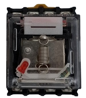
The Omron MK2P-N is a versatile and robust electromagnetic relay designed for a wide range of control applications. This relay is known for its reliability and durability, making it a popular choice in industrial settings. It can be used to control various loads, including motors, lights, and heaters, by providing a means to switch higher power circuits with a low power signal.
Explore Projects Built with Relay Omron MK2P-N
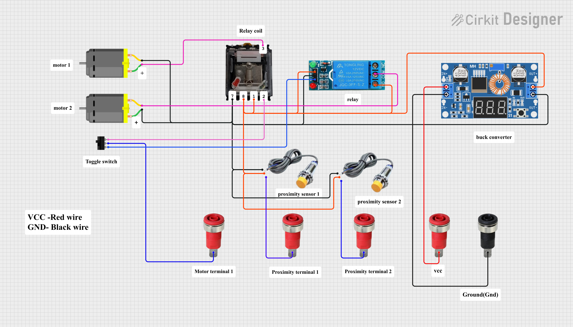

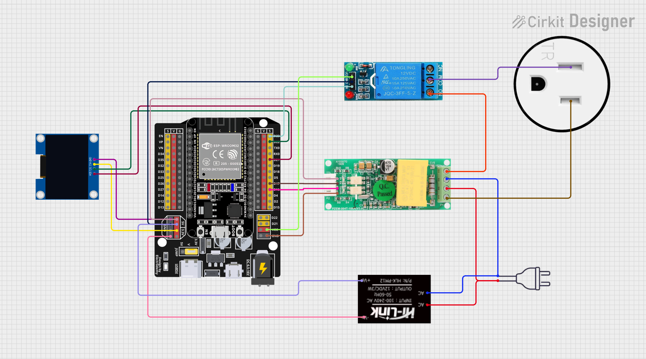

Explore Projects Built with Relay Omron MK2P-N
Common Applications and Use Cases
- Industrial automation systems
- Motor control circuits
- Lighting control systems
- HVAC systems
- Safety and security equipment
Technical Specifications
Key Technical Details
- Contact Configuration: DPDT (Double Pole Double Throw)
- Contact Rating: 10A at 250VAC, 10A at 30VDC
- Coil Voltage: Available in various standard voltages (e.g., 12VDC, 24VDC, 110VAC, 220VAC)
- Coil Power Consumption: Approx. 2.5VA (AC), 2.0W (DC)
- Operate Time: 25ms max.
- Release Time: 25ms max.
- Mechanical Endurance: 10 million operations
- Electrical Endurance: 100,000 operations at rated load
Pin Configuration and Descriptions
| Pin Number | Description |
|---|---|
| 1, 8 | Coil Pins (A1, A2) |
| 2, 7 | Contact 1 (NO, NC) |
| 3, 6 | Contact 2 (NO, NC) |
| 4, 5 | Common Pins (COM) |
- NO: Normally Open Contact
- NC: Normally Closed Contact
- COM: Common Contact
Usage Instructions
How to Use the Component in a Circuit
- Identify the Coil Pins: Connect the coil pins (1 and 8) to the control circuit that will activate the relay. Ensure the voltage applied matches the coil voltage rating.
- Connect the Load: Attach the device you wish to control to the NO or NC contacts (2, 7 for Contact 1 and 3, 6 for Contact 2) and the corresponding COM pins (4, 5).
- Power the Circuit: Once the relay is properly wired, apply power to the control circuit to activate the relay and switch the connected load.
Important Considerations and Best Practices
- Voltage Matching: Always match the coil voltage to the control signal voltage to prevent damage.
- Current Rating: Do not exceed the contact current rating to avoid contact damage or relay failure.
- Inductive Loads: When controlling inductive loads, consider using a flyback diode to prevent back EMF damage.
- Mounting: Use a suitable relay socket for easy installation and replacement.
- Testing: Test the relay in your specific application under controlled conditions before full deployment.
Troubleshooting and FAQs
Common Issues
- Relay Not Activating: Check the control circuit voltage and connections to the coil pins.
- Intermittent Operation: Verify that the contacts are not worn out and that the load does not exceed the rated current.
- Noise Issues: Ensure proper grounding and consider using a snubber circuit if necessary.
Solutions and Tips
- Coil Voltage: If the relay does not activate, double-check that the coil voltage is correct and that the control circuit is functioning.
- Contact Wear: If the relay is used frequently, monitor for signs of contact wear and replace the relay if necessary.
- Load Rating: Always confirm that the load does not exceed the relay's rated capacity.
FAQs
Q: Can the Omron MK2P-N be used with an Arduino? A: Yes, the relay can be interfaced with an Arduino, but ensure that the coil voltage is compatible and use a transistor or relay driver module if necessary.
Q: How can I extend the life of the relay? A: Avoid switching loads that exceed the relay's rating and use protective circuits for inductive loads.
Q: What is the purpose of the mechanical indicator? A: The mechanical indicator provides a visual confirmation of the relay's operation, which is useful for troubleshooting and testing.
Example Arduino Code
Below is an example of how to control the Omron MK2P-N relay with an Arduino UNO. This example assumes the use of a relay driver module to safely interface with the relay.
// Define the pin connected to the relay module
const int relayPin = 2;

void setup() {
  // Set the relay pin as an output
  pinMode(relayPin, OUTPUT);
}

void loop() {
  // Turn on the relay (activate the connected load)
  digitalWrite(relayPin, HIGH);
  delay(1000); // Wait for 1 second

  // Turn off the relay (deactivate the connected load)
  digitalWrite(relayPin, LOW);
  delay(1000); // Wait for 1 second
}
Note: The above code is a simple example. In a real-world application, you would need to consider the full control logic and safety measures. Always ensure that the Arduino's output pin is not directly driving the relay coil, as the current requirements may exceed the Arduino's capabilities. Use a relay driver module or a transistor with a flyback diode to safely control the relay.