How to Use HW040: Examples, Pinouts, and Specs
Introduction
The HW040 is a versatile microcontroller module designed for a wide range of embedded applications. It features multiple input/output (I/O) ports, various communication interfaces, and low power consumption, making it an ideal choice for projects requiring efficient and reliable operation. The HW040 is suitable for applications such as home automation, IoT devices, robotics, and industrial control systems.
Explore Projects Built with HW040


Explore Projects Built with HW040
Technical Specifications
The HW040 microcontroller module is equipped with the following key specifications:
General Specifications
- Processor: 32-bit ARM Cortex-M4 core
- Operating Voltage: 3.3V
- Clock Speed: 72 MHz
- Flash Memory: 256 KB
- SRAM: 64 KB
- Power Consumption: < 50 mA (active mode), < 1 mA (sleep mode)
- Communication Interfaces: UART, SPI, I2C, CAN
- GPIO Pins: 32 configurable pins
- ADC Resolution: 12-bit, up to 16 channels
- PWM Channels: 8
- Operating Temperature: -40°C to 85°C
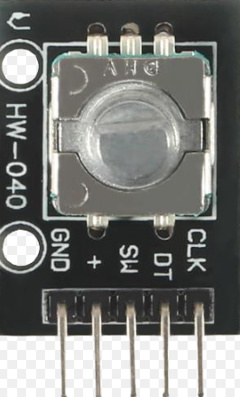
Pin Configuration and Descriptions
The HW040 module has a total of 40 pins, with the following configuration:
| Pin Number | Pin Name | Description |
|---|---|---|
| 1 | VCC | Power supply input (3.3V) |
| 2 | GND | Ground |
| 3 | GPIO1 | General-purpose I/O pin 1 |
| 4 | GPIO2 | General-purpose I/O pin 2 |
| 5 | GPIO3 | General-purpose I/O pin 3 |
| 6 | GPIO4 | General-purpose I/O pin 4 |
| 7 | UART_TX | UART transmit |
| 8 | UART_RX | UART receive |
| 9 | SPI_MOSI | SPI Master Out Slave In |
| 10 | SPI_MISO | SPI Master In Slave Out |
| 11 | SPI_SCK | SPI clock |
| 12 | SPI_CS | SPI chip select |
| 13 | I2C_SCL | I2C clock |
| 14 | I2C_SDA | I2C data |
| 15 | ADC_IN1 | Analog-to-digital converter input 1 |
| 16 | ADC_IN2 | Analog-to-digital converter input 2 |
| 17-32 | GPIO5-20 | Additional general-purpose I/O pins |
| 33 | PWM1 | PWM output channel 1 |
| 34 | PWM2 | PWM output channel 2 |
| 35 | CAN_TX | CAN bus transmit |
| 36 | CAN_RX | CAN bus receive |
| 37 | RESET | Reset pin |
| 38 | BOOT | Bootloader mode selection |
| 39 | NC | Not connected |
| 40 | NC | Not connected |
Usage Instructions
How to Use the HW040 in a Circuit
- Power Supply: Connect the VCC pin to a 3.3V power source and the GND pin to ground.
- I/O Configuration: Configure the GPIO pins as input or output based on your application. Use pull-up or pull-down resistors if necessary.
- Communication Interfaces:
- For UART communication, connect the UART_TX and UART_RX pins to the corresponding pins on your device.
- For SPI, connect SPI_MOSI, SPI_MISO, SPI_SCK, and SPI_CS to the SPI interface of your device.
- For I2C, connect I2C_SCL and I2C_SDA to the I2C bus.
- Analog Inputs: Use the ADC_IN pins for analog signal input. Ensure the input voltage does not exceed 3.3V.
- PWM Outputs: Connect the PWM pins to devices such as motors or LEDs for pulse-width modulation control.
Important Considerations and Best Practices
- Ensure the power supply voltage is stable and within the specified range (3.3V).
- Use decoupling capacitors (e.g., 0.1 µF) near the VCC pin to reduce noise.
- Avoid leaving unused pins floating; connect them to ground or configure them as inputs with pull-up/down resistors.
- For high-speed communication, use proper termination resistors for SPI and CAN interfaces.
- When using the bootloader mode, connect the BOOT pin to the appropriate logic level as specified in the datasheet.
Example: Connecting HW040 to an Arduino UNO
The HW040 can be interfaced with an Arduino UNO via UART. Below is an example code snippet:
// Example: Communicating with HW040 via UART
// Connect HW040 UART_TX to Arduino RX (Pin 0)
// Connect HW040 UART_RX to Arduino TX (Pin 1)
// Ensure both devices share a common ground

void setup() {
  Serial.begin(9600); // Initialize UART communication at 9600 baud
  delay(1000);        // Wait for HW040 to initialize
  Serial.println("Hello, HW040!"); // Send a test message
}

void loop() {
  if (Serial.available()) {
    // Read data from HW040 and echo it back
    char data = Serial.read();
    Serial.print("Received: ");
    Serial.println(data);
  }
}
Troubleshooting and FAQs
Common Issues and Solutions
No Response from HW040:
- Ensure the power supply is correctly connected and providing 3.3V.
- Verify that the RESET pin is not held low.
- Check the UART connections and baud rate settings.
Communication Errors:
- For UART, ensure the TX and RX pins are correctly connected.
- For SPI or I2C, verify the clock and data lines are properly connected and terminated.
Analog Input Not Working:
- Ensure the input voltage to ADC_IN pins does not exceed 3.3V.
- Check for proper grounding and signal conditioning.
PWM Output Issues:
- Verify the PWM frequency and duty cycle settings in your code.
- Ensure the connected device (e.g., motor or LED) is compatible with the PWM signal.
FAQs
Q: Can the HW040 operate at 5V?
A: No, the HW040 is designed to operate at 3.3V. Using 5V may damage the module.Q: How do I update the firmware on the HW040?
A: Use the BOOT pin to enter bootloader mode and follow the firmware update procedure provided by the manufacturer.Q: Can I use all GPIO pins simultaneously?
A: Yes, but ensure the total current draw does not exceed the module's maximum rating.Q: Is the HW040 compatible with Arduino libraries?
A: Yes, the HW040 can be programmed using Arduino IDE if a compatible board definition is available.
By following this documentation, you can effectively integrate the HW040 into your projects and troubleshoot common issues.