
How to Use Compass Module - HMC6352: Examples, Pinouts, and Specs
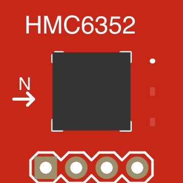
 Design with Compass Module - HMC6352 in Cirkit Designer
Introduction
The HMC6352 is a digital compass module manufactured by SparkFun, with the part ID HMC6352. It is designed to provide accurate heading information by detecting the Earth's magnetic field using an integrated magnetometer. The module outputs the heading in degrees, making it ideal for applications requiring precise orientation data.
Explore Projects Built with Compass Module - HMC6352
 Open Project in Cirkit Designer
 Open Project in Cirkit Designer
 Open Project in Cirkit Designer
 Open Project in Cirkit Designer
Explore Projects Built with Compass Module - HMC6352
Open Project in Cirkit DesignerOpen Project in Cirkit DesignerOpen Project in Cirkit DesignerOpen Project in Cirkit DesignerCommon Applications:
- Navigation systems
- Robotics and autonomous vehicles
- Drone stabilization and orientation
- Handheld devices with directional capabilities
- Geographic surveying and mapping tools
Technical Specifications
The HMC6352 is a compact and efficient module with the following key specifications:
| Parameter | Value |
|---|---|
| Supply Voltage | 2.7V to 5.2V |
| Operating Current | 1 mA (typical) |
| Standby Current | 25 µA |
| Communication Protocol | I²C |
| Heading Output Range | 0° to 359.9° |
| Heading Resolution | 0.1° |
| Accuracy | ±2° (typical) |
| Operating Temperature | -20°C to +70°C |
| Dimensions | 20.3mm x 20.3mm x 3.8mm |
Pin Configuration and Descriptions
The HMC6352 module has a 4-pin interface for power and communication. Below is the pinout:
| Pin | Name | Description |
|---|---|---|
| 1 | VCC | Power supply input (2.7V to 5.2V) |
| 2 | GND | Ground connection |
| 3 | SDA | I²C data line for communication |
| 4 | SCL | I²C clock line for communication |
Usage Instructions
Connecting the HMC6352 to a Circuit
- Power Supply: Connect the
VCCpin to a 3.3V or 5V power source and theGNDpin to the ground of your circuit. - I²C Communication: Connect the
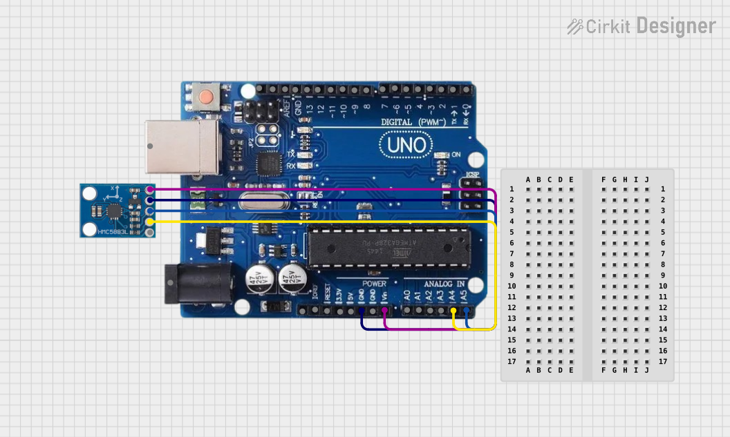
SDAandSCLpins to the corresponding I²C pins on your microcontroller (e.g., Arduino UNO). - Pull-Up Resistors: Ensure that the I²C lines (
SDAandSCL) have pull-up resistors (typically 4.7kΩ) if not already provided by your microcontroller.
Important Considerations
- Magnetic Interference: Avoid placing the module near ferromagnetic materials or strong magnetic fields, as they can distort the readings.
- Calibration: Perform a calibration routine if the module is used in a new environment to ensure accurate readings.
- Orientation: Mount the module flat and ensure it is aligned with the desired reference direction.
Example: Using HMC6352 with Arduino UNO
Below is an example code to interface the HMC6352 with an Arduino UNO and read the heading data:
#include <Wire.h> // Include the Wire library for I²C communication

#define HMC6352_ADDRESS 0x42 // I²C address of the HMC6352 module

void setup() {
  Wire.begin(); // Initialize I²C communication
  Serial.begin(9600); // Start serial communication for debugging

  // Send a command to the HMC6352 to enter continuous measurement mode
  Wire.beginTransmission(HMC6352_ADDRESS);
  Wire.write('A'); // 'A' command sets the module to continuous measurement mode
  Wire.endTransmission();
}

void loop() {
  int headingData; // Variable to store the heading data

  // Request 2 bytes of heading data from the HMC6352
  Wire.beginTransmission(HMC6352_ADDRESS);
  Wire.write('A'); // Request heading data
  Wire.endTransmission();
  delay(6); // Wait for the data to be ready

  Wire.requestFrom(HMC6352_ADDRESS, 2); // Request 2 bytes from the module
  if (Wire.available() >= 2) {
    // Read the two bytes and combine them into a single integer
    byte msb = Wire.read(); // Most significant byte
    byte lsb = Wire.read(); // Least significant byte
    headingData = (msb << 8) + lsb; // Combine MSB and LSB
    float heading = headingData / 10.0; // Convert to degrees (0.1° resolution)

    // Print the heading to the Serial Monitor
    Serial.print("Heading: ");
    Serial.print(heading);
    Serial.println("°");
  }

  delay(500); // Wait before the next reading
}
Notes:
- The I²C address of the HMC6352 is
0x42(7-bit address). - The heading data is returned in tenths of a degree (e.g., 1234 = 123.4°).
Troubleshooting and FAQs
Common Issues
No Data Received:
- Ensure the
SDAandSCLlines are correctly connected. - Verify that pull-up resistors are present on the I²C lines.
- Check the power supply voltage (2.7V to 5.2V).
- Ensure the
Inaccurate Readings:
- Perform a calibration routine to account for local magnetic interference.
- Ensure the module is mounted away from ferromagnetic materials.
Module Not Responding:
- Confirm the I²C address (
0x42) is correct. - Check for loose or incorrect wiring.
- Confirm the I²C address (
FAQs
Q: Can the HMC6352 operate at 5V?
A: Yes, the module supports a supply voltage range of 2.7V to 5.2V.
Q: How do I calibrate the HMC6352?
A: The HMC6352 has a built-in calibration mode. Refer to the manufacturer's datasheet for detailed calibration instructions.
Q: What is the maximum I²C clock speed supported?
A: The HMC6352 supports I²C clock speeds up to 100kHz.
Q: Can I use the HMC6352 outdoors?
A: Yes, but ensure it is protected from extreme temperatures and environmental factors like moisture.
By following this documentation, you can effectively integrate the HMC6352 compass module into your projects and troubleshoot common issues.