
How to Use Grove Infrared Emitter: Examples, Pinouts, and Specs
 Design with Grove Infrared Emitter in Cirkit Designer
Introduction
The Grove Infrared Emitter, manufactured by Seeed Studio, is a compact and efficient device designed to emit infrared (IR) light. It is commonly used in remote control applications, such as controlling TVs, air conditioners, and other appliances. Additionally, it can be used for communication between devices, such as transmitting data to an IR receiver module. The Grove Infrared Emitter is part of the Grove ecosystem, making it easy to integrate with other Grove modules and microcontrollers like the Arduino UNO.
Explore Projects Built with Grove Infrared Emitter
 Open Project in Cirkit Designer
 Open Project in Cirkit Designer
 Open Project in Cirkit Designer
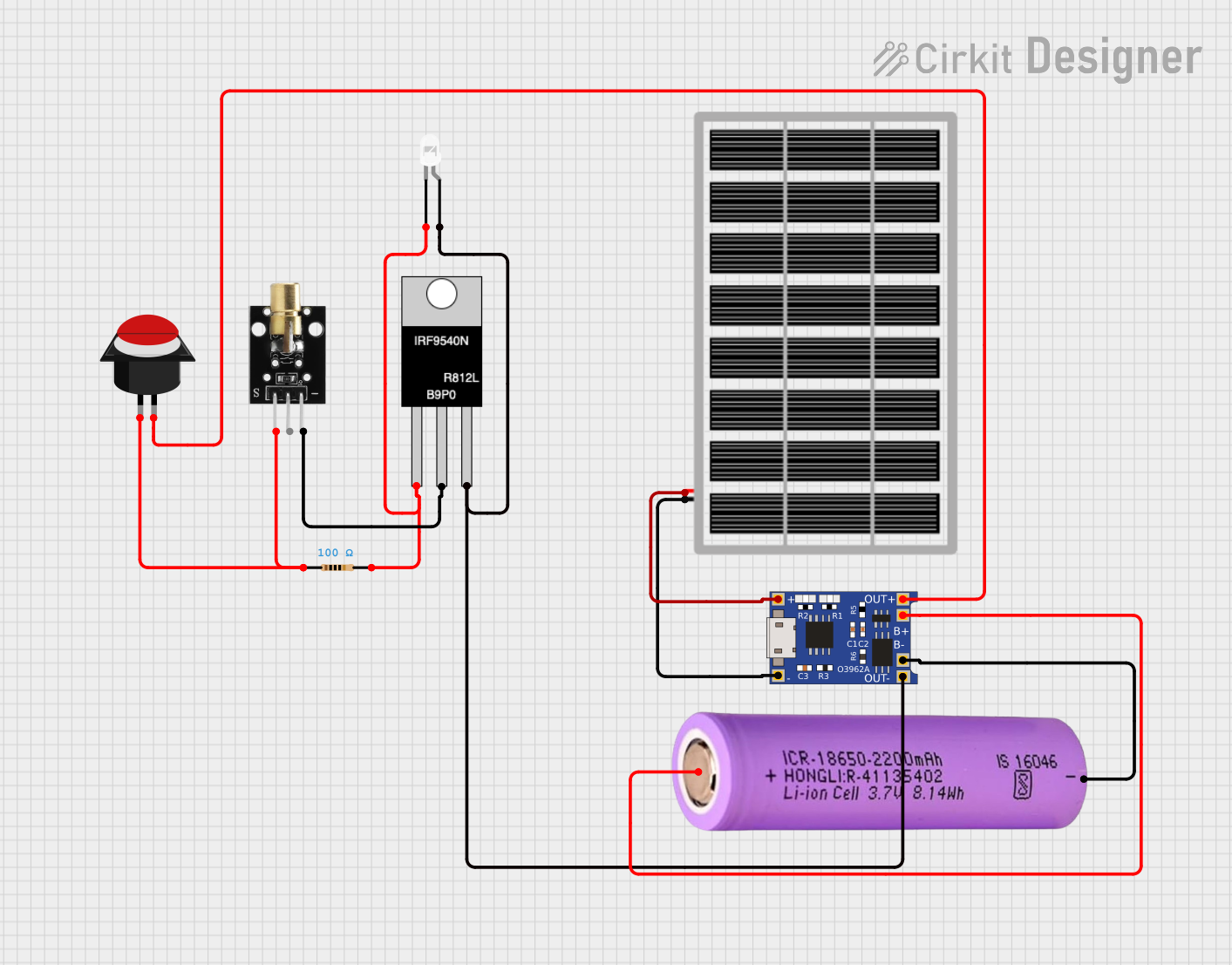 Open Project in Cirkit Designer
Explore Projects Built with Grove Infrared Emitter
Open Project in Cirkit DesignerOpen Project in Cirkit DesignerOpen Project in Cirkit DesignerOpen Project in Cirkit DesignerTechnical Specifications
The following table outlines the key technical details of the Grove Infrared Emitter:
| Parameter | Value |
|---|---|
| Operating Voltage | 3.3V / 5V |
| Operating Current | ≤ 20mA |
| Wavelength | 940nm (Infrared Light) |
| Emission Angle | ±15° |
| Communication Protocol | GPIO (Digital Signal) |
| Dimensions | 20mm x 20mm |
| Connector Type | Grove 4-pin interface |
Pin Configuration
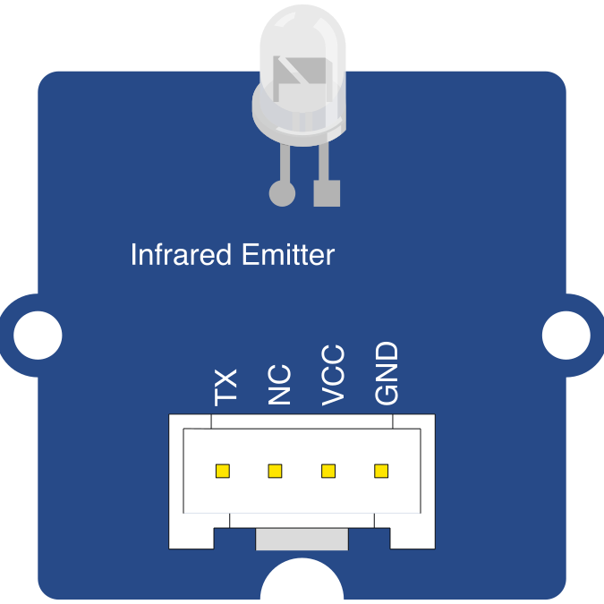
The Grove Infrared Emitter uses a 4-pin Grove connector. The pin configuration is as follows:
| Pin | Label | Description |
|---|---|---|
| 1 | VCC | Power supply (3.3V or 5V) |
| 2 | GND | Ground |
| 3 | NC | Not connected |
| 4 | SIG | Signal input (digital control pin) |
Usage Instructions
How to Use the Grove Infrared Emitter in a Circuit
- Connect the Module: Use a Grove cable to connect the Infrared Emitter to a Grove Base Shield attached to an Arduino UNO or other compatible microcontroller.
- Power the Module: Ensure the module is powered with 3.3V or 5V, depending on your microcontroller's output.
- Control the Signal: Use a digital GPIO pin to send a HIGH or LOW signal to the SIG pin. A HIGH signal will activate the IR LED, emitting infrared light.
- Pair with an IR Receiver: For communication purposes, pair the emitter with a compatible IR receiver module to send and receive data.
Important Considerations and Best Practices
- Line of Sight: Ensure there is a clear line of sight between the IR emitter and the target device or receiver for optimal performance.
- Power Supply: Use a stable power supply to avoid fluctuations that could affect the IR signal.
- Signal Modulation: For remote control applications, modulate the signal at a frequency of 38kHz, as most IR receivers are tuned to this frequency.
- Avoid Overheating: Do not exceed the recommended operating current of 20mA to prevent damage to the IR LED.
Example Code for Arduino UNO
The following example demonstrates how to use the Grove Infrared Emitter with an Arduino UNO to send a modulated IR signal:
// Include the IRremote library for signal modulation
#include <IRremote.h>

// Define the digital pin connected to the SIG pin of the IR emitter
const int irEmitterPin = 3;

void setup() {
  // Initialize the IR emitter pin as an output
  pinMode(irEmitterPin, OUTPUT);

  // Initialize the IRremote library
  IrSender.begin(irEmitterPin, ENABLE_LED_FEEDBACK);
}

void loop() {
  // Send a 38kHz modulated IR signal with a custom data pattern
  // Replace 0x1FE48B7 with the desired IR code
  IrSender.sendNEC(0x1FE48B7, 32);

  // Wait for 2 seconds before sending the next signal
  delay(2000);
}
Note: Install the
IRremotelibrary in the Arduino IDE before uploading the code. You can do this via the Library Manager.
Troubleshooting and FAQs
Common Issues and Solutions
No IR Signal Detected
- Cause: Incorrect wiring or loose connections.
- Solution: Double-check the Grove cable connections and ensure the module is securely attached to the Base Shield.
IR Signal Not Reaching Target Device
- Cause: Obstructions or incorrect alignment.
- Solution: Ensure there is a clear line of sight between the emitter and the target device. Adjust the angle of the emitter if necessary.
IR Emitter Overheating
- Cause: Exceeding the recommended operating current.
- Solution: Verify that the current does not exceed 20mA. Use a current-limiting resistor if needed.
Target Device Not Responding
- Cause: Incorrect signal modulation frequency.
- Solution: Ensure the signal is modulated at 38kHz for compatibility with most IR receivers.
FAQs
Q: Can the Grove Infrared Emitter be used with microcontrollers other than Arduino?
A: Yes, the module can be used with any microcontroller that supports digital GPIO control, such as Raspberry Pi or ESP32.
Q: How can I verify that the IR emitter is working?
A: Use a smartphone camera to view the IR LED while it is active. The camera can detect infrared light, which will appear as a faint purple glow.
Q: What is the maximum range of the IR emitter?
A: The range depends on the power of the IR LED and the sensitivity of the receiver. Typically, it can reach up to 5 meters in optimal conditions.
Q: Can I use the Grove Infrared Emitter for data communication?
A: Yes, the emitter can transmit data to an IR receiver module. Ensure proper signal modulation and encoding for reliable communication.