How to Use OBD II: Examples, Pinouts, and Specs
Introduction
On-Board Diagnostics II (OBD II) is a standardized system implemented in most vehicles manufactured after 1996. It is designed to monitor and report on the performance of the engine, emissions systems, and other critical vehicle components. OBD II provides diagnostic information through a standardized 16-pin connector, enabling mechanics, technicians, and even hobbyists to access trouble codes and real-time vehicle data for troubleshooting, maintenance, and emissions testing.
Explore Projects Built with OBD II
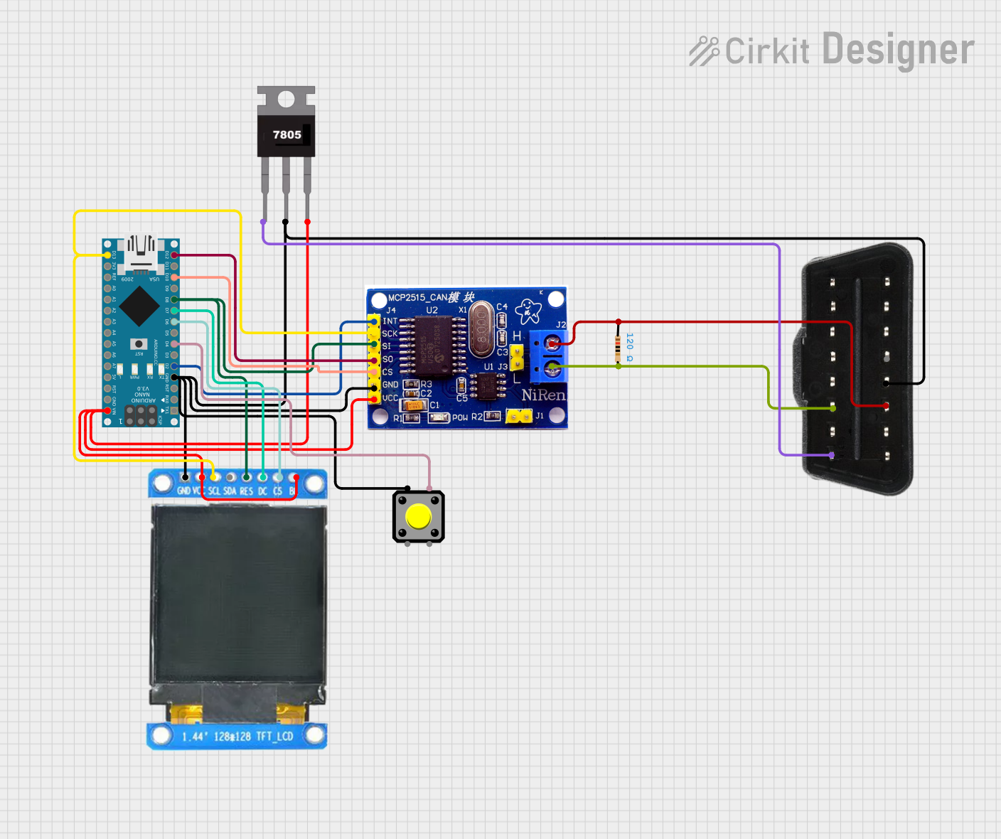
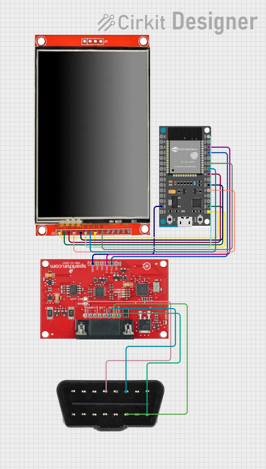
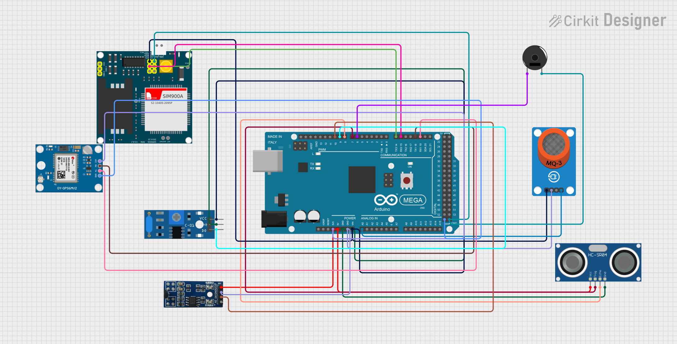
Explore Projects Built with OBD II
Common Applications and Use Cases
- Vehicle Diagnostics: Reading and clearing Diagnostic Trouble Codes (DTCs).
- Emissions Testing: Ensuring compliance with environmental regulations.
- Performance Monitoring: Accessing real-time data such as speed, RPM, and fuel efficiency.
- Custom Applications: Developing custom dashboards or vehicle monitoring systems using microcontrollers like Arduino or Raspberry Pi.
Technical Specifications
Key Technical Details
- Connector Type: 16-pin standardized OBD II connector.
- Communication Protocols:
- SAE J1850 PWM (Pulse Width Modulation)
- SAE J1850 VPW (Variable Pulse Width)
- ISO 9141-2
- ISO 14230-4 (KWP2000)
- ISO 15765-4 (CAN bus)
- Voltage Levels:
- Operating Voltage: 12V DC (typical for most vehicles).
- Signal Voltage: 5V logic levels for data communication.
- Data Rate: Varies by protocol (e.g., CAN bus supports up to 1 Mbps).
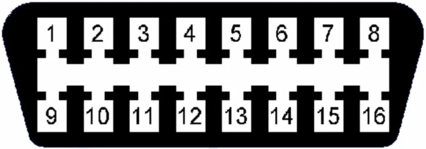
- Pinout: Standardized 16-pin layout.
Pin Configuration and Descriptions
The OBD II connector has a standardized pinout. Below is the pin configuration:
| Pin Number | Name | Description |
|---|---|---|
| 1 | Manufacturer-Specific | Reserved for OEM-specific functions. |
| 2 | J1850 Bus+ | Positive line for SAE J1850 PWM/VPW communication. |
| 3 | Manufacturer-Specific | Reserved for OEM-specific functions. |
| 4 | Chassis Ground | Ground connection for the vehicle's chassis. |
| 5 | Signal Ground | Ground connection for signal reference. |
| 6 | CAN High (J-2284) | High line for CAN bus communication. |
| 7 | ISO 9141-2 K-Line | Data line for ISO 9141-2 and KWP2000 protocols. |
| 8 | Manufacturer-Specific | Reserved for OEM-specific functions. |
| 9 | Manufacturer-Specific | Reserved for OEM-specific functions. |
| 10 | J1850 Bus- | Negative line for SAE J1850 PWM communication. |
| 11 | Manufacturer-Specific | Reserved for OEM-specific functions. |
| 12 | Manufacturer-Specific | Reserved for OEM-specific functions. |
| 13 | Manufacturer-Specific | Reserved for OEM-specific functions. |
| 14 | CAN Low (J-2284) | Low line for CAN bus communication. |
| 15 | ISO 9141-2 L-Line | Optional line for ISO 9141-2 and KWP2000 protocols. |
| 16 | Battery Power | Direct connection to the vehicle's battery (12V). |
Usage Instructions
How to Use the OBD II in a Circuit
Connect the OBD II Adapter:
- Use an OBD II-to-USB or OBD II-to-serial adapter to interface with a computer or microcontroller.
- Ensure the adapter supports the communication protocol used by your vehicle (e.g., CAN, ISO 9141-2).
Power the Circuit:
- The OBD II connector provides 12V power on Pin 16 and ground on Pin 4 or Pin 5.
- If using a microcontroller, use a voltage regulator to step down the 12V to 5V or 3.3V as required.
Read Data:
- Use an OBD II library or software to send commands and read data.
- For example, the "010C" PID (Parameter ID) retrieves the engine RPM.
Interpret Data:
- Refer to the OBD II standard for a list of PIDs and their meanings.
- Use the data for diagnostics, performance monitoring, or custom applications.
Important Considerations and Best Practices
- Protocol Compatibility: Ensure your adapter or microcontroller supports the protocol used by your vehicle.
- Safety: Avoid short circuits or incorrect wiring, as the OBD II port is directly connected to the vehicle's electrical system.
- Data Logging: Use appropriate software or libraries to log data for analysis.
- Legal Compliance: Ensure your use of OBD II data complies with local regulations, especially for emissions testing.
Example: Using OBD II with Arduino UNO
Below is an example of how to read engine RPM using an Arduino UNO and an OBD II adapter:
#include <OBD2.h> // Include an OBD II library for Arduino

OBD2 obd; // Create an OBD2 object

void setup() {
  Serial.begin(9600); // Initialize serial communication
  obd.begin(); // Initialize OBD II communication

  if (obd.connect()) {
    Serial.println("OBD II connected successfully!");
  } else {
    Serial.println("Failed to connect to OBD II.");
  }
}

void loop() {
  int rpm = obd.readPID(0x0C); // Read the engine RPM (PID 0x0C)

  if (rpm >= 0) {
    Serial.print("Engine RPM: ");
    Serial.println(rpm);
  } else {
    Serial.println("Failed to read RPM.");
  }

  delay(1000); // Wait 1 second before the next reading
}
Troubleshooting and FAQs
Common Issues and Solutions
OBD II Adapter Not Connecting:
- Cause: Incorrect protocol or faulty adapter.
- Solution: Verify the protocol used by your vehicle and ensure the adapter supports it.
No Data or Incorrect Data:
- Cause: Loose connection or unsupported PID.
- Solution: Check the wiring and ensure the requested PID is supported by your vehicle.
Microcontroller Not Responding:
- Cause: Voltage mismatch or incorrect library usage.
- Solution: Use a voltage regulator to step down 12V to 5V or 3.3V. Verify the library documentation.
FAQs
Q: Can I damage my vehicle using the OBD II port?
A: Yes, improper wiring or short circuits can damage the vehicle's electrical system. Always double-check connections.Q: What vehicles support OBD II?
A: Most vehicles manufactured after 1996 in the U.S. and similar regulations in other countries.Q: Can I use OBD II data for custom applications?
A: Yes, OBD II data can be used for custom dashboards, performance monitoring, and more, provided it complies with local laws.Q: How do I know which protocol my vehicle uses?
A: Check the vehicle's manual or use an OBD II adapter that automatically detects the protocol.