How to Use Basler a2A1920-51gcPro: Examples, Pinouts, and Specs
Introduction
The Basler a2A1920-51gcPro is a high-performance industrial camera designed for demanding machine vision applications. Manufactured by Basler, this camera offers exceptional image quality and reliability, making it a popular choice for automation, quality inspection, and object recognition tasks. With its 1920x1200 pixel resolution, global shutter technology, and GigE interface, the a2A1920-51gcPro is capable of capturing fast-moving objects with precision and transferring data at high speeds.
Explore Projects Built with Basler a2A1920-51gcPro

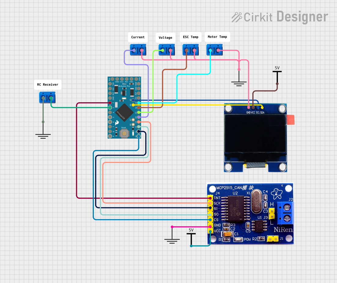
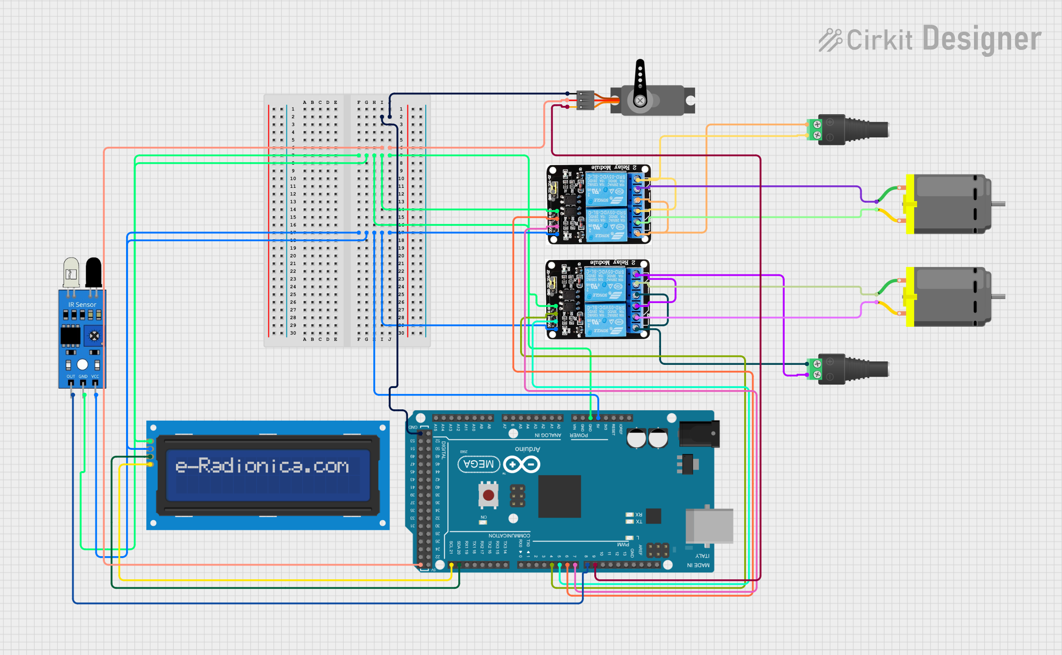
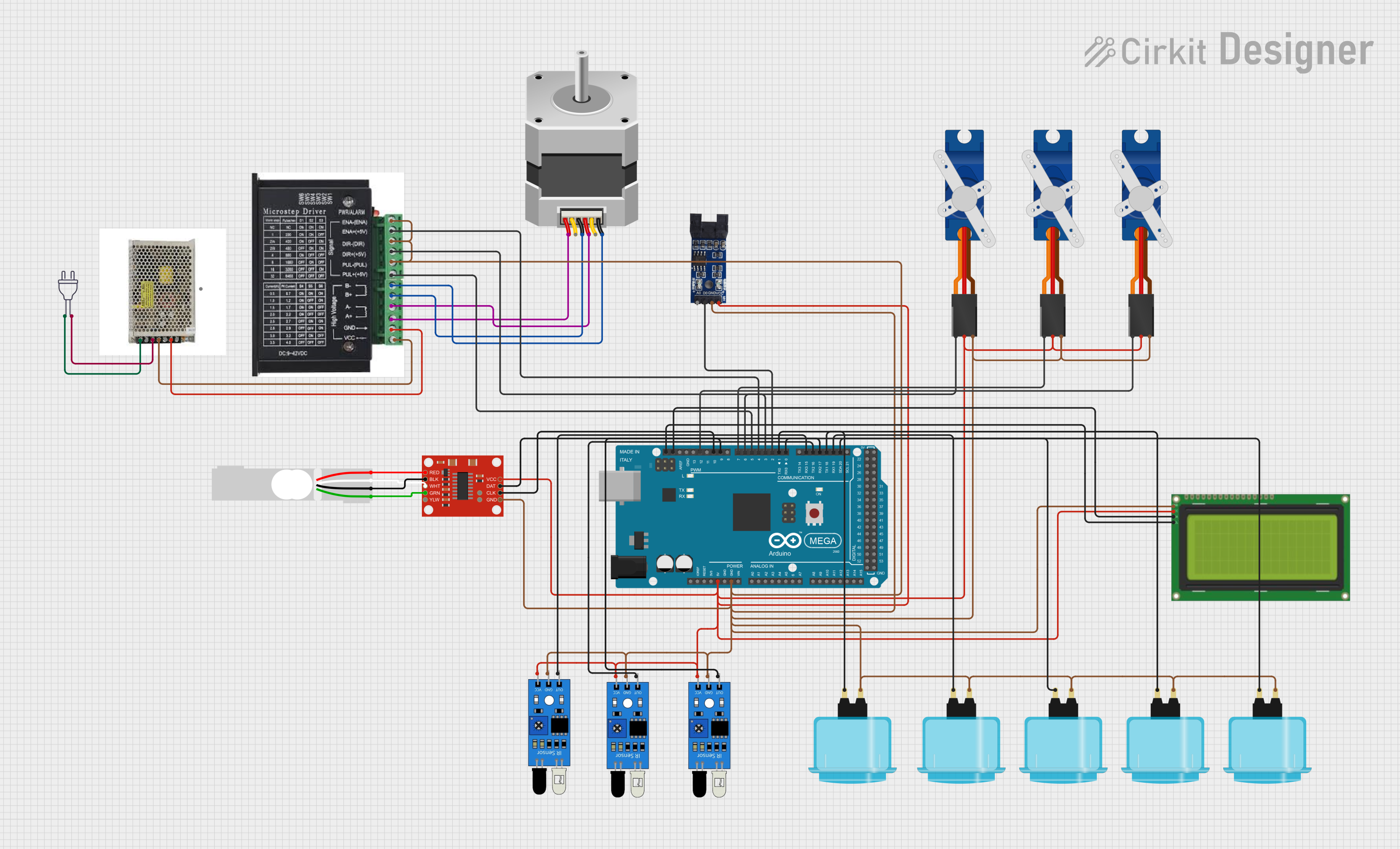
Explore Projects Built with Basler a2A1920-51gcPro
Common Applications and Use Cases
- Quality Inspection: Detecting defects or irregularities in manufacturing processes.
- Object Recognition: Identifying and classifying objects in industrial automation systems.
- Robotics: Enabling vision-guided robotic systems for precise operations.
- Medical Imaging: Supporting diagnostic equipment with high-resolution imaging.
- Traffic Monitoring: Capturing high-speed vehicles for traffic enforcement or analysis.
Technical Specifications
The following table outlines the key technical details of the Basler a2A1920-51gcPro:
| Specification | Details |
|---|---|
| Resolution | 1920 x 1200 pixels (2.3 MP) |
| Sensor Type | CMOS with global shutter |
| Frame Rate | Up to 51 frames per second (fps) |
| Pixel Size | 5.86 µm x 5.86 µm |
| Interface | Gigabit Ethernet (GigE) |
| Lens Mount | C-mount |
| Power Supply | Power over Ethernet (PoE) or external 12-24V DC |
| Operating Temperature | -20°C to 65°C |
| Dimensions | 29 mm x 29 mm x 42 mm |
| Weight | Approx. 90 g |
Pin Configuration and Descriptions
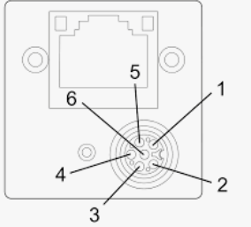
The Basler a2A1920-51gcPro uses a standard GigE interface for data transfer and power. Below is the pin configuration for the I/O connector:
| Pin Number | Signal Name | Description |
|---|---|---|
| 1 | Power Input (VCC) | External power supply input (12-24V DC) |
| 2 | Ground (GND) | Ground connection |
| 3 | Trigger Input | External trigger signal for image capture |
| 4 | Strobe Output | Output signal for synchronizing external devices (e.g., flash) |
| 5 | GPIO1 | General-purpose input/output pin |
| 6 | GPIO2 | General-purpose input/output pin |
Usage Instructions
How to Use the Component in a Circuit
- Power Supply: Connect the camera to a Power over Ethernet (PoE) switch or provide an external 12-24V DC power supply to the power input pin.
- Data Connection: Use a Cat5e or Cat6 Ethernet cable to connect the camera to a computer or network switch.
- Lens Installation: Attach a compatible C-mount lens to the camera. Ensure the lens is securely fastened.
- Trigger and GPIO: If required, connect external devices (e.g., triggers, strobes) to the I/O connector using the pin configuration table above.
- Software Setup: Install Basler's pylon Camera Software Suite on your computer. This software provides tools for camera configuration, image acquisition, and development.
Important Considerations and Best Practices
- Lens Selection: Choose a lens with appropriate focal length and aperture for your application.
- Cable Length: For GigE connections, ensure the Ethernet cable length does not exceed 100 meters.
- Heat Management: Operate the camera within the specified temperature range (-20°C to 65°C) to avoid overheating.
- Trigger Configuration: Use the pylon software to configure trigger modes and GPIO functionality as needed.
- Firmware Updates: Regularly check for firmware updates on the Basler website to ensure optimal performance.
Example Code for Arduino UNO Integration
While the Basler a2A1920-51gcPro is typically used with PCs, it can also interface with microcontrollers like the Arduino UNO for basic trigger control. Below is an example of how to send a trigger signal to the camera:
// Example: Sending a trigger signal to the Basler a2A1920-51gcPro
// Connect Arduino pin 7 to the camera's Trigger Input pin (Pin 3 on I/O connector)

const int triggerPin = 7; // Define the Arduino pin connected to the camera trigger

void setup() {
  pinMode(triggerPin, OUTPUT); // Set the trigger pin as an output
  digitalWrite(triggerPin, LOW); // Initialize the trigger pin to LOW
}

void loop() {
  // Send a HIGH pulse to trigger the camera
  digitalWrite(triggerPin, HIGH);
  delay(10); // Keep the signal HIGH for 10 milliseconds
  digitalWrite(triggerPin, LOW);

  // Wait for 1 second before sending the next trigger
  delay(1000);
}
Note: Ensure the trigger voltage levels are compatible with the camera's input specifications.
Troubleshooting and FAQs
Common Issues and Solutions
No Image Output:
- Cause: Incorrect network configuration or cable connection.
- Solution: Verify the Ethernet cable connection and ensure the camera is detected in the pylon software.
Camera Overheating:
- Cause: Operating in a high-temperature environment.
- Solution: Use the camera within the specified temperature range and ensure proper ventilation.
Trigger Not Working:
- Cause: Incorrect trigger signal or configuration.
- Solution: Check the trigger voltage levels and configure the trigger mode in the pylon software.
Low Frame Rate:
- Cause: Network bandwidth limitations or incorrect settings.
- Solution: Use a dedicated GigE network and optimize camera settings in the pylon software.
FAQs
Q: Can the camera be powered solely via PoE?
- A: Yes, the camera supports Power over Ethernet (PoE) for both power and data transfer.
Q: What is the maximum cable length for GigE?
- A: The maximum cable length is 100 meters when using Cat5e or Cat6 Ethernet cables.
Q: Is the camera compatible with third-party software?
- A: Yes, the camera supports third-party software via the GenICam standard.
Q: Can the camera capture color images?
- A: Yes, the a2A1920-51gcPro is available in both monochrome and color variants.
This concludes the documentation for the Basler a2A1920-51gcPro. For further assistance, refer to the official Basler user manual or contact their technical support.