Cirkit Designer Logo
Cirkit Designer
Your all-in-one circuit design IDE
Home / 
Component Documentation

How to Use RXB12 RF Receiver: Examples, Pinouts, and Specs

Image of RXB12 RF Receiver
Cirkit Designer LogoDesign with RXB12 RF Receiver in Cirkit Designer

Introduction

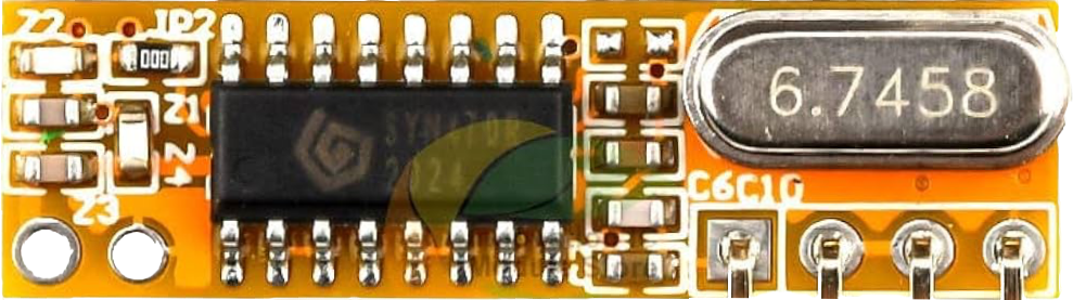
The RXB12 RF Receiver is a compact radio frequency receiver module designed for wireless communication applications. It operates at a frequency of 433.92 MHz, which is a common frequency for remote control devices such as garage door openers, car key fobs, and wireless home automation systems. The RXB12 is known for its low power consumption and high sensitivity, making it a popular choice for battery-operated devices.

Explore Projects Built with RXB12 RF Receiver

Use Cirkit Designer to design, explore, and prototype these projects online. Some projects support real-time simulation. Click "Open Project" to start designing instantly!
Arduino UNO with 433MHz RF Module for Wireless Communication
Image of Receiver: A project utilizing RXB12 RF Receiver in a practical application
This circuit consists of an Arduino UNO connected to an RXN433MHz radio frequency module. The Arduino provides 5V power and ground to the RF module and is configured to communicate with it via digital pin D11. Additionally, a multimeter is connected with alligator clip cables to measure the voltage supplied to the RF module.
Cirkit Designer LogoOpen Project in Cirkit Designer
ESP32-Based RF Communication System with 433 MHz Modules
Image of 433 mhz: A project utilizing RXB12 RF Receiver in a practical application
This circuit comprises an ESP32 microcontroller connected to a 433 MHz RF transmitter and receiver pair. The ESP32 is programmed to receive and decode RF signals through the receiver module, as well as send RF signals via the transmitter module. Additionally, the ESP32 can communicate with a Bluetooth device to exchange commands and data, and it uses an LED for status indication.
Cirkit Designer LogoOpen Project in Cirkit Designer
Battery-Powered nRF52840 and HT-RA62 Communication Module
Image of NRF52840+HT-RA62: A project utilizing RXB12 RF Receiver in a practical application
This circuit is a wireless communication system powered by a 18650 Li-ion battery, featuring an nRF52840 ProMicro microcontroller and an HT-RA62 transceiver module. The nRF52840 handles the control logic and interfaces with the HT-RA62 for data transmission, while the battery provides the necessary power for the entire setup.
Cirkit Designer LogoOpen Project in Cirkit Designer
Satellite-Based Timing and Navigation System with SDR and Atomic Clock Synchronization
Image of GPS 시스템 측정 구성도_Confirm: A project utilizing RXB12 RF Receiver in a practical application
This circuit appears to be a complex system involving power supply management, GPS and timing synchronization, and data communication. It includes a SI-TEX G1 Satellite Compass for GPS data, an XHTF1021 Atomic Rubidium Clock for precise timing, and Ettus USRP B200 units for software-defined radio communication. Power is supplied through various SMPS units and distributed via terminal blocks and DC jacks. Data communication is facilitated by Beelink MINI S12 N95 computers, RS232 splitters, and a 1000BASE-T Media Converter for network connectivity. RF Directional Couplers are used to interface antennas with the USRP units, and the entire system is likely contained within cases for protection and organization.
Cirkit Designer LogoOpen Project in Cirkit Designer

Explore Projects Built with RXB12 RF Receiver

Use Cirkit Designer to design, explore, and prototype these projects online. Some projects support real-time simulation. Click "Open Project" to start designing instantly!
Image of Receiver: A project utilizing RXB12 RF Receiver in a practical application
Arduino UNO with 433MHz RF Module for Wireless Communication
This circuit consists of an Arduino UNO connected to an RXN433MHz radio frequency module. The Arduino provides 5V power and ground to the RF module and is configured to communicate with it via digital pin D11. Additionally, a multimeter is connected with alligator clip cables to measure the voltage supplied to the RF module.
Cirkit Designer LogoOpen Project in Cirkit Designer
Image of 433 mhz: A project utilizing RXB12 RF Receiver in a practical application
ESP32-Based RF Communication System with 433 MHz Modules
This circuit comprises an ESP32 microcontroller connected to a 433 MHz RF transmitter and receiver pair. The ESP32 is programmed to receive and decode RF signals through the receiver module, as well as send RF signals via the transmitter module. Additionally, the ESP32 can communicate with a Bluetooth device to exchange commands and data, and it uses an LED for status indication.
Cirkit Designer LogoOpen Project in Cirkit Designer
Image of NRF52840+HT-RA62: A project utilizing RXB12 RF Receiver in a practical application
Battery-Powered nRF52840 and HT-RA62 Communication Module
This circuit is a wireless communication system powered by a 18650 Li-ion battery, featuring an nRF52840 ProMicro microcontroller and an HT-RA62 transceiver module. The nRF52840 handles the control logic and interfaces with the HT-RA62 for data transmission, while the battery provides the necessary power for the entire setup.
Cirkit Designer LogoOpen Project in Cirkit Designer
Image of GPS 시스템 측정 구성도_Confirm: A project utilizing RXB12 RF Receiver in a practical application
Satellite-Based Timing and Navigation System with SDR and Atomic Clock Synchronization
This circuit appears to be a complex system involving power supply management, GPS and timing synchronization, and data communication. It includes a SI-TEX G1 Satellite Compass for GPS data, an XHTF1021 Atomic Rubidium Clock for precise timing, and Ettus USRP B200 units for software-defined radio communication. Power is supplied through various SMPS units and distributed via terminal blocks and DC jacks. Data communication is facilitated by Beelink MINI S12 N95 computers, RS232 splitters, and a 1000BASE-T Media Converter for network connectivity. RF Directional Couplers are used to interface antennas with the USRP units, and the entire system is likely contained within cases for protection and organization.
Cirkit Designer LogoOpen Project in Cirkit Designer

Common Applications and Use Cases

  • Remote control systems
  • Wireless data transmission
  • Home automation
  • Security systems
  • Industrial controls

Technical Specifications

Key Technical Details

  • Operating Frequency: 433.92 MHz
  • Supply Voltage: 2.1V to 5.5V
  • Operating Current: 2.5mA (typical at 5V)
  • Sensitivity: -110dBm (at 2kbps)
  • Operating Temperature: -40°C to +85°C

Pin Configuration and Descriptions

Pin Number Pin Name Description
1 ANT Antenna connection
2 GND Ground
3 VCC Power supply (2.1V to 5.5V)
4 DATA Data output
5 GND Ground (optional for improved stability)

Usage Instructions

How to Use the Component in a Circuit

  1. Connect the ANT pin to an antenna suitable for the 433.92 MHz frequency.
  2. Connect the VCC pin to a power supply between 2.1V and 5.5V.
  3. Connect the GND pin to the ground of the power supply.
  4. The DATA pin outputs the demodulated data signal, which can be connected to a microcontroller or other data processing unit.

Important Considerations and Best Practices

  • Ensure that the power supply is stable and within the specified voltage range.
  • Use a proper 433.92 MHz antenna for optimal reception.
  • Keep the receiver away from metal objects and noise sources for better performance.
  • For noise-sensitive applications, a decoupling capacitor (e.g., 100nF) between VCC and GND is recommended.

Example Connection with Arduino UNO

// RXB12 RF Receiver to Arduino UNO connection
// RXB12 Pin 4 (DATA) to Arduino Pin 2 (Interrupt 0)

void setup() {
  pinMode(2, INPUT); // Set the data pin as input
  attachInterrupt(0, dataReceived, CHANGE); // Attach interrupt for data reception
}

void loop() {
  // Main loop can be used to perform other tasks
}

// Interrupt service routine for handling received data
void dataReceived() {
  // Code to handle the received data
}

Troubleshooting and FAQs

Common Issues

  • No Signal Detected: Ensure the antenna is properly connected and there are no obstructions or interference sources nearby.
  • Intermittent Signal: Check for loose connections and consider adding a decoupling capacitor to stabilize the power supply.
  • Weak Signal: Position the antenna away from metal objects and adjust its orientation for better reception.

Solutions and Tips for Troubleshooting

  • Verify that the power supply voltage is within the specified range.
  • Check solder joints and wiring for any loose connections or shorts.
  • Use a multimeter to measure the voltage at the VCC and GND pins to ensure proper power is being supplied.
  • If using with a microcontroller, ensure that the data pin is configured correctly and that the interrupt service routine is properly set up.

FAQs

Q: Can the RXB12 be used with other frequencies? A: No, the RXB12 is specifically tuned for the 433.92 MHz frequency.

Q: What is the range of the RXB12 RF Receiver? A: The range depends on several factors including antenna type, power supply voltage, and environmental conditions. Under ideal conditions, it can typically receive signals from up to 100 meters away.

Q: Can the RXB12 be used with any microcontroller? A: Yes, the RXB12 can be interfaced with any microcontroller that has digital input pins capable of reading the data signal.

Q: Is it necessary to use both GND pins? A: While it is not strictly necessary, using both GND pins can improve the stability of the connection, especially in noisy environments.