How to Use ESP8266 Witty Cloud: Examples, Pinouts, and Specs
Introduction
The ESP8266 Witty Cloud is a Wi-Fi microcontroller module developed by Espressif. It is designed for Internet of Things (IoT) applications, offering a compact design, GPIO pins for interfacing with external devices, and an integrated USB interface for easy programming. The module is based on the ESP8266 chip, which provides robust Wi-Fi connectivity and a programmable microcontroller core.
Explore Projects Built with ESP8266 Witty Cloud
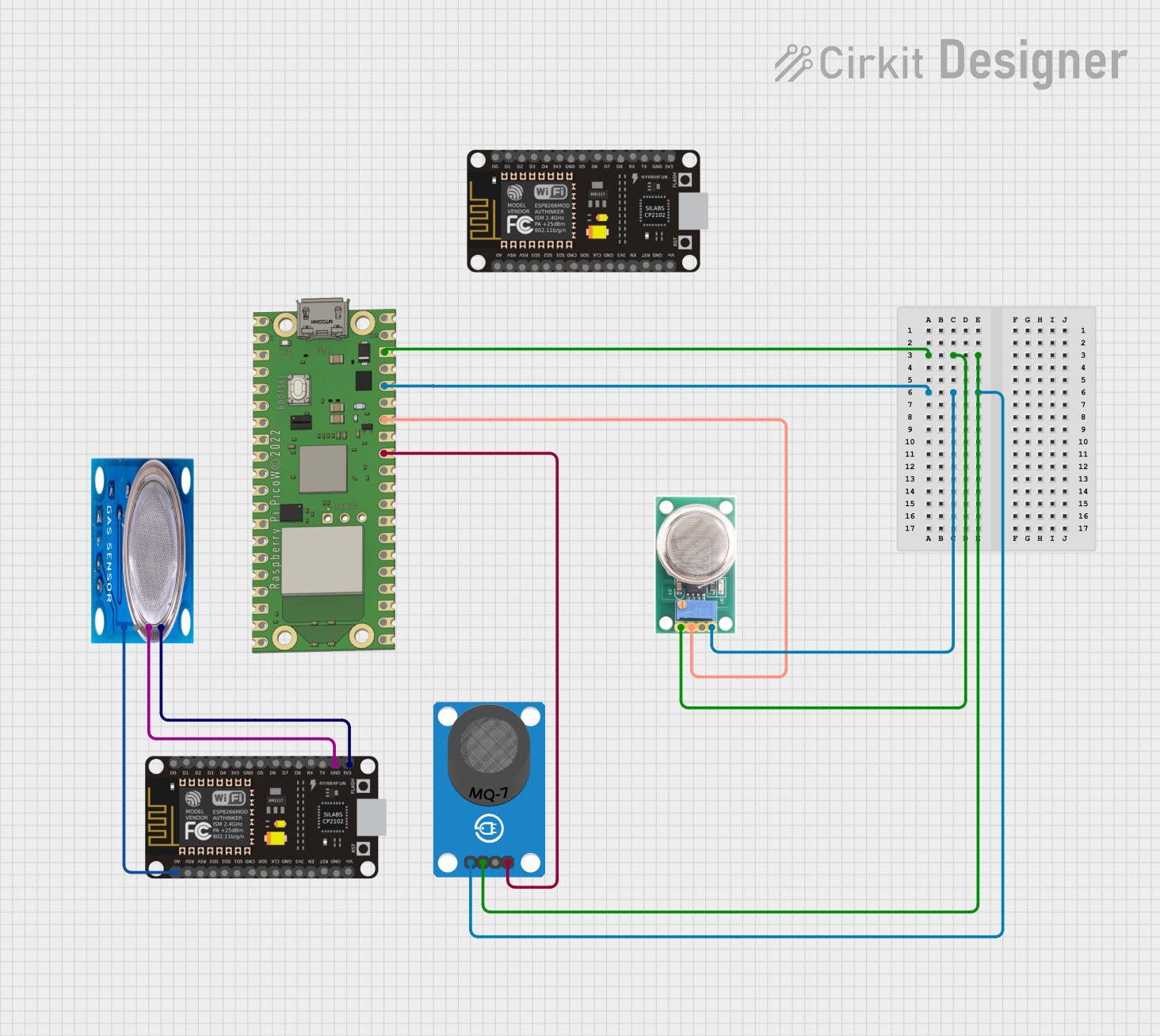
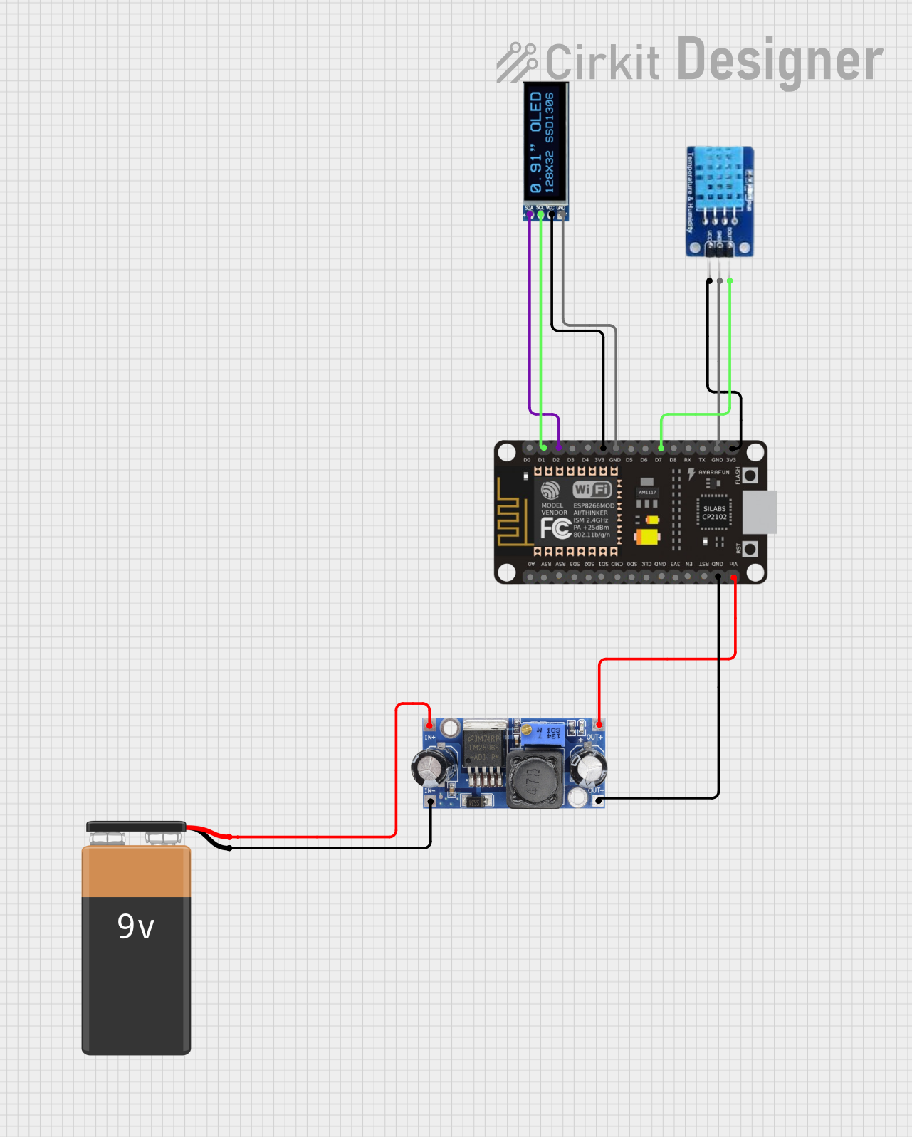
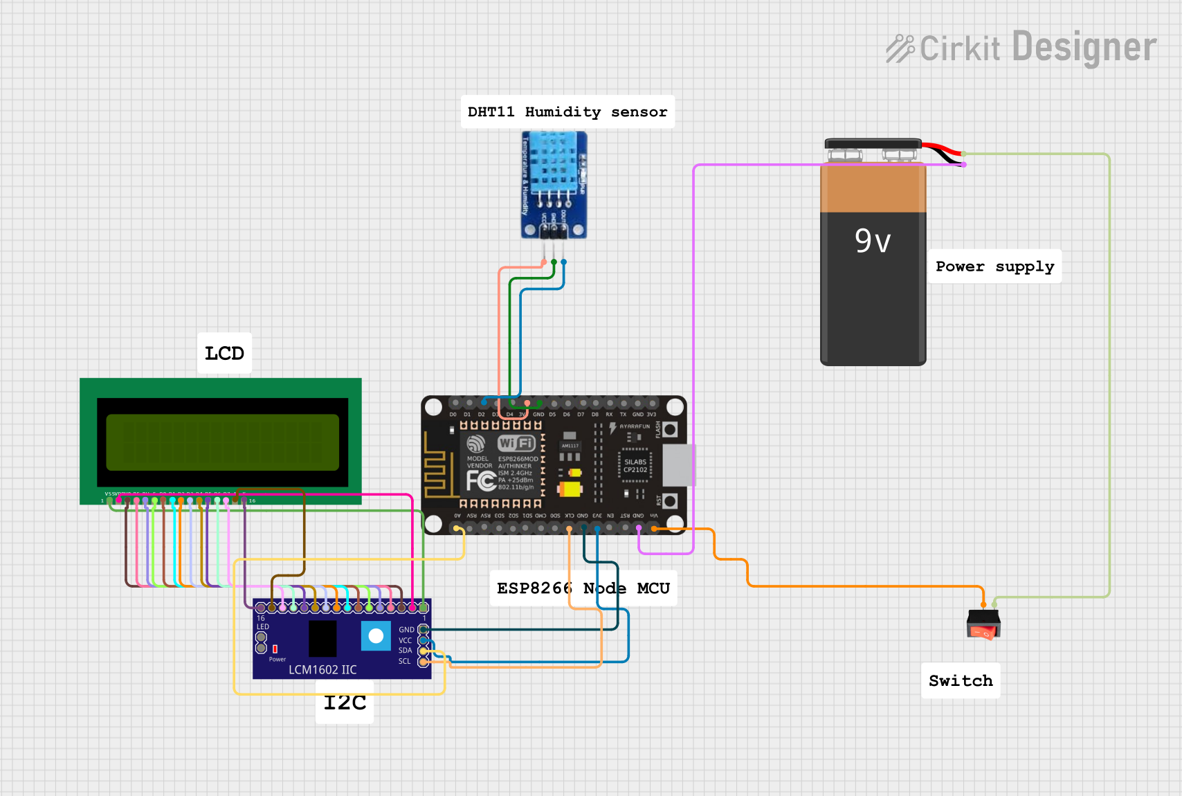

Explore Projects Built with ESP8266 Witty Cloud
Common Applications and Use Cases
- Home automation systems
- IoT sensor nodes
- Wireless data logging
- Smart lighting control
- Remote monitoring and control systems
- Prototyping and educational projects
Technical Specifications
Key Technical Details
| Parameter | Value |
|---|---|
| Microcontroller | ESP8266 |
| Wi-Fi Standard | 802.11 b/g/n |
| Operating Voltage | 3.3V |
| Input Voltage (via USB) | 5V |
| Flash Memory | 4MB |
| GPIO Pins | 11 |
| ADC Resolution | 10-bit |
| Maximum Current Draw | ~200mA |
| Operating Temperature | -40°C to 125°C |
| Dimensions | 25mm x 25mm |
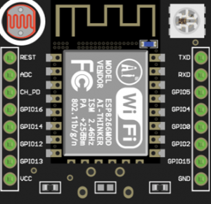
Pin Configuration and Descriptions
The ESP8266 Witty Cloud module has two boards: the main ESP8266 board and a baseboard with a USB interface. Below is the pin configuration for the main ESP8266 board:
| Pin Name | Description |
|---|---|
| VCC | Power input (3.3V) |
| GND | Ground |
| TX | UART Transmit (for serial communication) |
| RX | UART Receive (for serial communication) |
| GPIO0 | General-purpose I/O pin (used for boot mode) |
| GPIO2 | General-purpose I/O pin |
| GPIO4 | General-purpose I/O pin |
| GPIO5 | General-purpose I/O pin |
| GPIO12 | General-purpose I/O pin |
| GPIO13 | General-purpose I/O pin |
| GPIO14 | General-purpose I/O pin |
| GPIO15 | General-purpose I/O pin |
| ADC | Analog-to-digital converter input (0-1V range) |
Usage Instructions
How to Use the ESP8266 Witty Cloud in a Circuit
Powering the Module:
- Connect the module to a 5V USB power source via the baseboard.
- Alternatively, supply 3.3V directly to the VCC pin on the main board.
Programming the Module:
- Use the integrated USB interface to connect the module to your computer.
- Install the necessary USB-to-serial drivers (e.g., CH340 or CP2102, depending on the baseboard).
- Use the Arduino IDE or other compatible software to upload code to the module.
Connecting to Wi-Fi:
- Use the ESP8266's built-in Wi-Fi library to connect to a network.
- Ensure the SSID and password are correctly configured in your code.
Interfacing with GPIO Pins:
- Use the GPIO pins to connect sensors, LEDs, or other peripherals.
- Be mindful of the 3.3V logic level when interfacing with external devices.
Important Considerations and Best Practices
- Voltage Levels: The ESP8266 operates at 3.3V. Avoid applying 5V to the GPIO pins to prevent damage.
- Boot Modes: GPIO0, GPIO2, and GPIO15 determine the boot mode. Ensure these pins are correctly configured during startup.
- Heat Management: The module can get warm during operation. Ensure adequate ventilation in your design.
- ADC Input Range: The ADC pin accepts a maximum voltage of 1V. Use a voltage divider if necessary.
Example Code for Arduino UNO
Below is an example of how to connect the ESP8266 Witty Cloud to a Wi-Fi network and send data to a server:
#include <ESP8266WiFi.h> // Include the ESP8266 Wi-Fi library

// Replace with your network credentials
const char* ssid = "Your_SSID";
const char* password = "Your_PASSWORD";

void setup() {
  Serial.begin(115200); // Initialize serial communication at 115200 baud
  WiFi.begin(ssid, password); // Connect to Wi-Fi network

  Serial.print("Connecting to Wi-Fi");
  while (WiFi.status() != WL_CONNECTED) {
    delay(500); // Wait for connection
    Serial.print(".");
  }
  Serial.println("\nConnected to Wi-Fi!");
  Serial.print("IP Address: ");
  Serial.println(WiFi.localIP()); // Print the module's IP address
}

void loop() {
  // Add your main code here
}
Troubleshooting and FAQs
Common Issues and Solutions
Module Not Connecting to Wi-Fi:
- Double-check the SSID and password in your code.
- Ensure the router is within range and supports 2.4GHz Wi-Fi (the ESP8266 does not support 5GHz).
Serial Communication Not Working:
- Verify the correct COM port is selected in the Arduino IDE.
- Ensure the baud rate in the Serial Monitor matches the code (e.g., 115200).
Module Not Powering On:
- Check the power supply voltage (3.3V for VCC or 5V via USB).
- Ensure the USB cable is functional and properly connected.
GPIO Pins Not Responding:
- Confirm the pins are correctly configured in your code.
- Check for any short circuits or incorrect wiring.
FAQs
Q: Can I use the ESP8266 Witty Cloud with a 5V logic microcontroller?
A: Yes, but you will need a logic level shifter to safely interface the 3.3V GPIO pins with 5V logic.
Q: How do I reset the module?
A: Press the reset button on the baseboard or toggle the power supply.
Q: What is the maximum range of the Wi-Fi connection?
A: The range depends on environmental factors but is typically around 30-50 meters indoors and up to 100 meters outdoors.
Q: Can I use the module without the baseboard?
A: Yes, you can power the module directly via the VCC and GND pins and program it using an external USB-to-serial adapter.
By following this documentation, you can effectively integrate the ESP8266 Witty Cloud into your IoT projects.