How to Use GPS NEO 6M: Examples, Pinouts, and Specs
Introduction
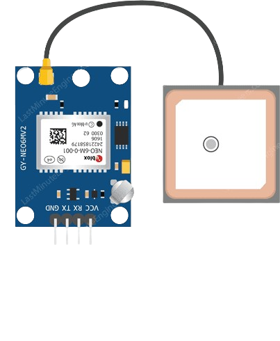
The GPS NEO 6M is a high-performance GPS module designed to provide accurate positioning data. It features a built-in ceramic antenna, low power consumption, and a compact design, making it ideal for a wide range of applications. The module supports communication via UART, making it easy to interface with microcontrollers and development boards like the Arduino UNO.
Explore Projects Built with GPS NEO 6M


Explore Projects Built with GPS NEO 6M
Common Applications and Use Cases
- Robotics and autonomous vehicles
- Drones and UAVs
- Navigation systems
- Geographic data logging
- Time synchronization for IoT devices
Technical Specifications
The GPS NEO 6M module is equipped with advanced features to ensure reliable and precise GPS data acquisition. Below are its key technical specifications:
Key Technical Details
| Parameter | Specification |
|---|---|
| Operating Voltage | 2.7V to 3.6V (3.3V recommended) |
| Input Voltage (via VCC) | 3.3V to 5V |
| Current Consumption | 45mA (typical) |
| Communication Interface | UART (default baud rate: 9600 bps) |
| Positioning Accuracy | 2.5 meters CEP |
| Update Rate | 1 Hz (default), configurable up to 5 Hz |
| Cold Start Time | 27 seconds (typical) |
| Hot Start Time | 1 second (typical) |
| Antenna | Built-in ceramic antenna |
| Operating Temperature | -40°C to +85°C |
| Dimensions | 16 x 12.2 x 2.4 mm |
Pin Configuration and Descriptions
The GPS NEO 6M module typically comes with a 4-pin interface. Below is the pinout description:
| Pin Name | Pin Number | Description |
|---|---|---|
| VCC | 1 | Power supply input (3.3V to 5V) |
| GND | 2 | Ground connection |
| TX | 3 | UART Transmit pin (data output) |
| RX | 4 | UART Receive pin (data input) |
Usage Instructions
The GPS NEO 6M module is straightforward to use and can be easily integrated into a circuit. Below are the steps and considerations for using the module:
Connecting the GPS NEO 6M to an Arduino UNO
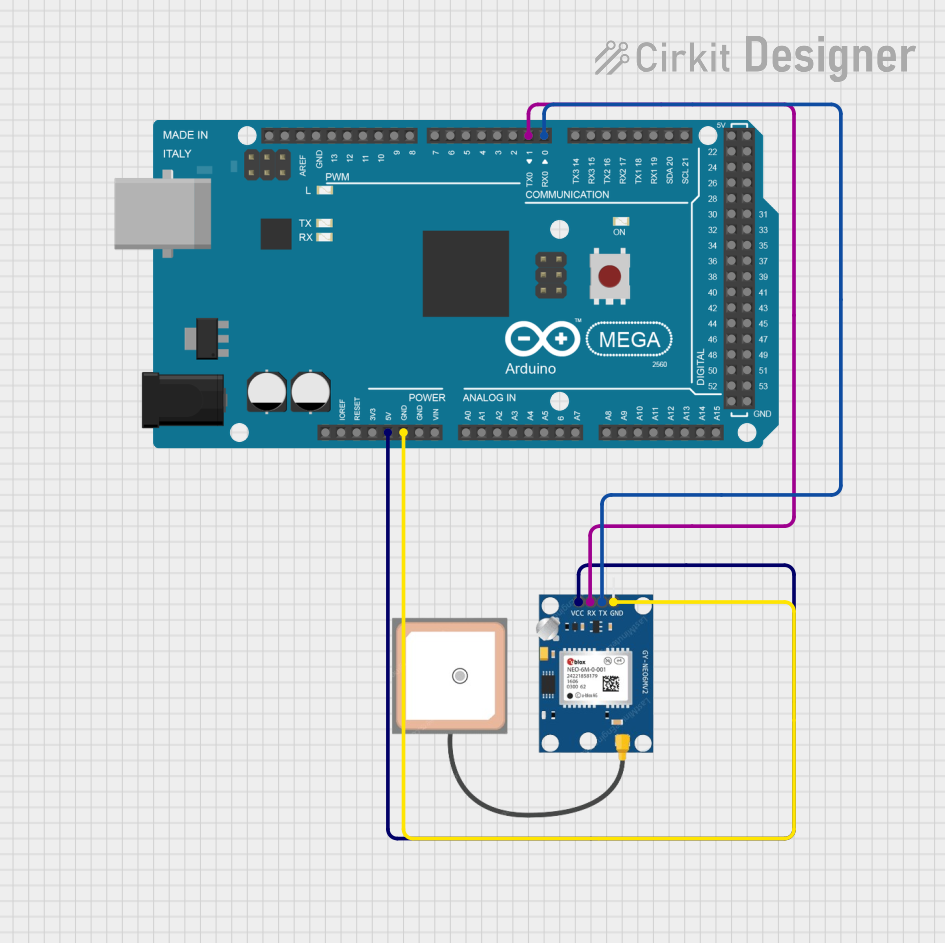
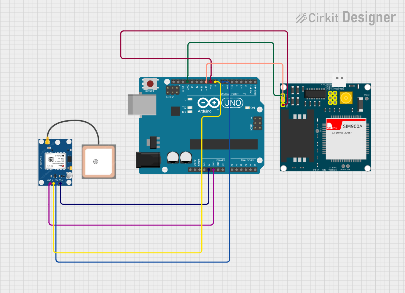
Wiring the Module:
- Connect the
VCCpin of the GPS module to the 5V pin on the Arduino UNO. - Connect the
GNDpin of the GPS module to the GND pin on the Arduino UNO. - Connect the
TXpin of the GPS module to the Arduino'sRXpin (pin 0). - Connect the
RXpin of the GPS module to the Arduino'sTXpin (pin 1).
- Connect the
Install Required Libraries:
- Install the
TinyGPS++library in the Arduino IDE for parsing GPS data. - Go to Sketch > Include Library > Manage Libraries, search for
TinyGPS++, and install it.
- Install the
Upload the Code: Use the following example code to read and display GPS data on the Serial Monitor:
#include <TinyGPS++.h>
#include <SoftwareSerial.h>

// Create a SoftwareSerial instance for communication with the GPS module
SoftwareSerial gpsSerial(4, 3); // RX, TX (connect to TX, RX of GPS module)

TinyGPSPlus gps; // Create a TinyGPS++ object

void setup() {
  Serial.begin(9600); // Initialize Serial Monitor
  gpsSerial.begin(9600); // Initialize GPS module communication
  Serial.println("GPS NEO 6M Test");
}

void loop() {
  // Read data from the GPS module
  while (gpsSerial.available() > 0) {
    char c = gpsSerial.read();
    // Feed the data into the TinyGPS++ library
    if (gps.encode(c)) {
      // If a valid GPS sentence is received, display the data
      if (gps.location.isUpdated()) {
        Serial.print("Latitude: ");
        Serial.print(gps.location.lat(), 6); // Print latitude
        Serial.print(", Longitude: ");
        Serial.println(gps.location.lng(), 6); // Print longitude
      }
    }
  }
}
Important Considerations and Best Practices
- Power Supply: Ensure the module is powered with a stable voltage (3.3V to 5V). Avoid voltage fluctuations to prevent data corruption.
- Antenna Placement: For optimal performance, place the module in an open area with a clear view of the sky to ensure strong satellite signals.
- UART Communication: Avoid using the Arduino's hardware UART (pins 0 and 1) for both GPS and Serial Monitor simultaneously. Use
SoftwareSerialfor GPS communication if needed. - Cold Start vs. Hot Start: The module may take longer to acquire a GPS fix during a cold start. For faster acquisition, ensure the module has access to satellite data from a previous session.
Troubleshooting and FAQs
Common Issues and Solutions
No GPS Fix (No Latitude/Longitude Data):
- Cause: Poor satellite signal or obstructed antenna placement.
- Solution: Move the module to an open area with a clear view of the sky. Ensure the antenna is not obstructed by metal objects.
Garbage Data on Serial Monitor:
- Cause: Mismatched baud rate between the GPS module and Arduino.
- Solution: Verify that the GPS module's baud rate is set to 9600 bps (default). Adjust the
gpsSerial.begin()baud rate in the code if necessary.
Module Not Powering On:
- Cause: Incorrect wiring or insufficient power supply.
- Solution: Double-check the connections and ensure the power supply voltage is within the specified range (3.3V to 5V).
Interference with Other Devices:
- Cause: Nearby electronic devices causing signal interference.
- Solution: Keep the GPS module away from high-frequency devices or sources of electromagnetic interference.
FAQs
Q1: Can the GPS NEO 6M work indoors?
A1: The module may work indoors but with reduced accuracy and reliability due to weak satellite signals. For best results, use it outdoors.
Q2: How can I increase the update rate of the GPS module?
A2: The update rate can be configured up to 5 Hz using specific NMEA commands. Refer to the module's datasheet for details.
Q3: Can I use the GPS NEO 6M with a 3.3V microcontroller?
A3: Yes, the module supports a 3.3V power supply and logic levels, making it compatible with 3.3V microcontrollers.
Q4: How do I log GPS data for later use?
A4: You can store GPS data on an SD card using an SD card module connected to your microcontroller. Combine the GPS and SD card libraries in your code.
By following this documentation, you can effectively integrate and use the GPS NEO 6M module in your projects.