Cirkit Designer Logo
Cirkit Designer
Your all-in-one circuit design IDE
Home / 
Component Documentation

How to Use LilyTiny: Examples, Pinouts, and Specs

Image of LilyTiny
Cirkit Designer LogoDesign with LilyTiny in Cirkit Designer

Introduction

The LilyTiny is a diminutive, programmable microcontroller board designed for integrating into wearable electronics and small projects. Its compact size and flexibility make it ideal for applications where space is at a premium and simplicity is key. The LilyTiny is often used in DIY e-textiles, interactive artwork, and educational projects to add functionality without the bulk of larger microcontroller boards.

Explore Projects Built with LilyTiny

Use Cirkit Designer to design, explore, and prototype these projects online. Some projects support real-time simulation. Click "Open Project" to start designing instantly!
LilyPad Arduino and Accelerometer-Based Wearable Fitness Tracker with Heart Rate Monitoring
Image of proj2: A project utilizing LilyTiny in a practical application
This circuit is designed for wearable applications, featuring a LilyPad Arduino USB microcontroller that controls a chain of LED Pixel Boards and reads data from a Heart Pulse Sensor and a three-axis Accelerometer. It is capable of interactive LED displays synchronized with motion and heart rate data, suitable for dynamic wearable projects.
Cirkit Designer LogoOpen Project in Cirkit Designer
Lilygo 7670e-Based Smart Interface with LCD Display and Keypad
Image of Paower: A project utilizing LilyTiny in a practical application
This circuit features a Lilygo 7670e microcontroller interfaced with a 16x2 I2C LCD for display, a 4X4 membrane matrix keypad for input, and an arcade button for additional control. It also includes a 4G antenna and a GPS antenna for communication and location tracking capabilities.
Cirkit Designer LogoOpen Project in Cirkit Designer
Cellular-Enabled IoT Device with Real-Time Clock and Power Management
Image of LRCM PHASE 2 BASIC: A project utilizing LilyTiny in a practical application
This circuit features a LilyGo-SIM7000G module for cellular communication and GPS functionality, interfaced with an RTC DS3231 for real-time clock capabilities. It includes voltage sensing through two voltage sensor modules, and uses an 8-channel opto-coupler for isolating different parts of the circuit. Power management is handled by a buck converter connected to a DC power source and batteries, with a fuse for protection and a rocker switch for on/off control. Additionally, there's an LED for indication purposes.
Cirkit Designer LogoOpen Project in Cirkit Designer
Bluetooth-Controlled Multi-Function Arduino Nano Gadget
Image of Copy of Smarttt: A project utilizing LilyTiny in a practical application
This is a portable, microcontroller-driven interactive device featuring Bluetooth connectivity, visual (RGB LED), auditory (loudspeaker), and haptic (vibration motor) feedback, user input (pushbutton), and a rechargeable power system (TP4056 with Li-ion battery).
Cirkit Designer LogoOpen Project in Cirkit Designer

Explore Projects Built with LilyTiny

Use Cirkit Designer to design, explore, and prototype these projects online. Some projects support real-time simulation. Click "Open Project" to start designing instantly!
Image of proj2: A project utilizing LilyTiny in a practical application
LilyPad Arduino and Accelerometer-Based Wearable Fitness Tracker with Heart Rate Monitoring
This circuit is designed for wearable applications, featuring a LilyPad Arduino USB microcontroller that controls a chain of LED Pixel Boards and reads data from a Heart Pulse Sensor and a three-axis Accelerometer. It is capable of interactive LED displays synchronized with motion and heart rate data, suitable for dynamic wearable projects.
Cirkit Designer LogoOpen Project in Cirkit Designer
Image of Paower: A project utilizing LilyTiny in a practical application
Lilygo 7670e-Based Smart Interface with LCD Display and Keypad
This circuit features a Lilygo 7670e microcontroller interfaced with a 16x2 I2C LCD for display, a 4X4 membrane matrix keypad for input, and an arcade button for additional control. It also includes a 4G antenna and a GPS antenna for communication and location tracking capabilities.
Cirkit Designer LogoOpen Project in Cirkit Designer
Image of LRCM PHASE 2 BASIC: A project utilizing LilyTiny in a practical application
Cellular-Enabled IoT Device with Real-Time Clock and Power Management
This circuit features a LilyGo-SIM7000G module for cellular communication and GPS functionality, interfaced with an RTC DS3231 for real-time clock capabilities. It includes voltage sensing through two voltage sensor modules, and uses an 8-channel opto-coupler for isolating different parts of the circuit. Power management is handled by a buck converter connected to a DC power source and batteries, with a fuse for protection and a rocker switch for on/off control. Additionally, there's an LED for indication purposes.
Cirkit Designer LogoOpen Project in Cirkit Designer
Image of Copy of Smarttt: A project utilizing LilyTiny in a practical application
Bluetooth-Controlled Multi-Function Arduino Nano Gadget
This is a portable, microcontroller-driven interactive device featuring Bluetooth connectivity, visual (RGB LED), auditory (loudspeaker), and haptic (vibration motor) feedback, user input (pushbutton), and a rechargeable power system (TP4056 with Li-ion battery).
Cirkit Designer LogoOpen Project in Cirkit Designer

Technical Specifications

Key Technical Details

  • Microcontroller: ATtiny85
  • Operating Voltage: 2.7V - 5.5V
  • Input Voltage (recommended): 2.7V - 5.5V
  • Digital I/O Pins: 5 (of which 2 are used for USB if reprogramming is required)
  • PWM Channels: 3
  • Analog Input Channels: 4
  • DC Current per I/O Pin: 40 mA
  • Flash Memory: 8 KB (ATtiny85) of which 2.75 KB used by bootloader
  • SRAM: 512 bytes
  • EEPROM: 512 bytes
  • Clock Speed: 8 MHz

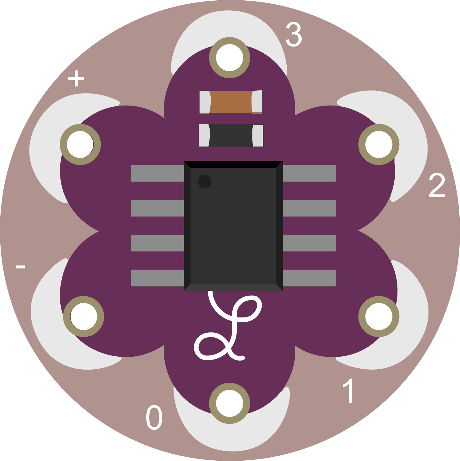
Pin Configuration and Descriptions

Pin Number Name Description
1 PB5 Reset and digital I/O, PWM
2 PB3 Analog input A3 and digital I/O, PWM
3 PB4 Analog input A2 and digital I/O
4 GND Ground
5 PB0 Analog input A0 and digital I/O, PWM
6 PB1 Analog input A1 and digital I/O
7 VCC Positive supply voltage
8 PB2 Analog input A1 and digital I/O

Usage Instructions

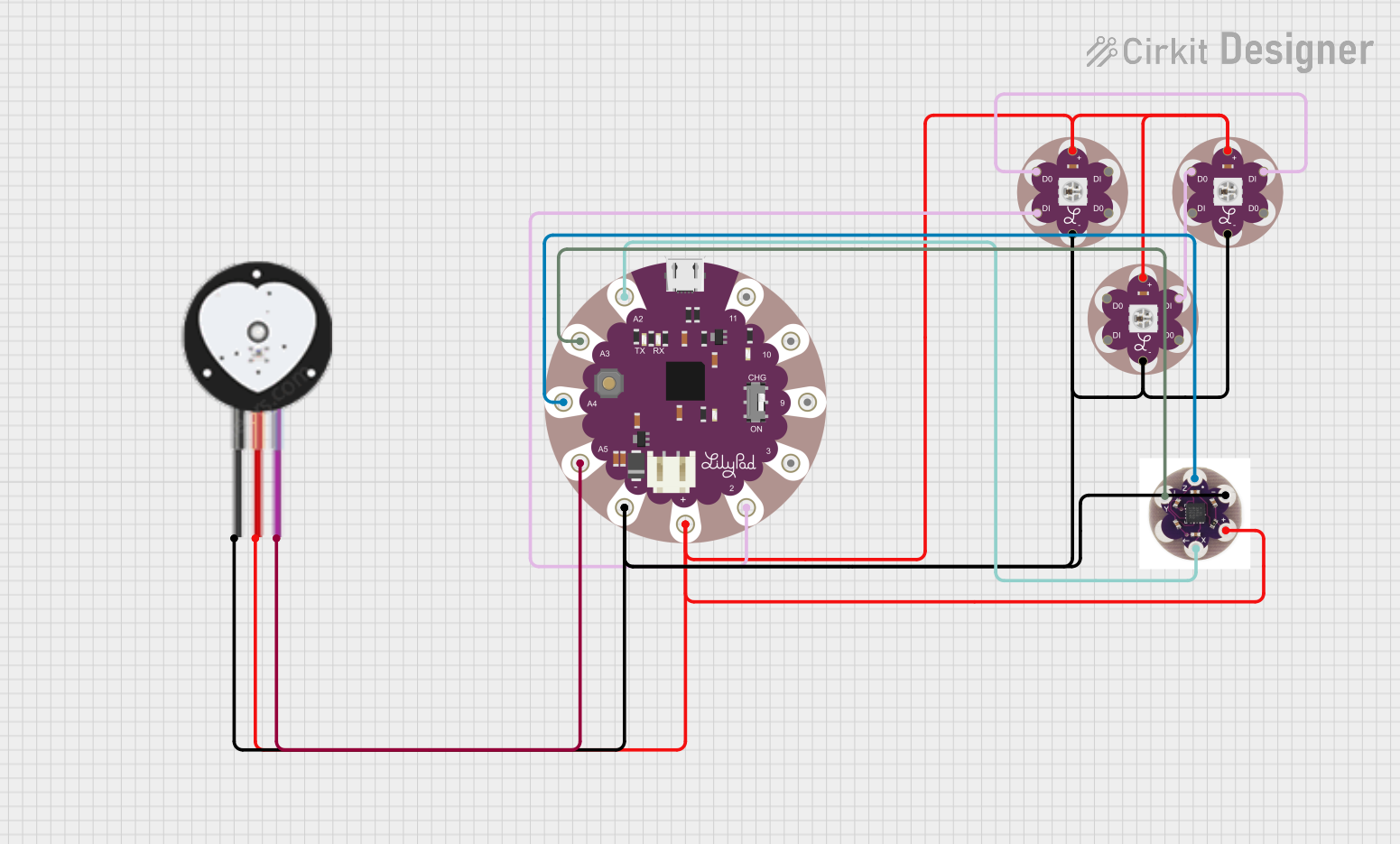
Integrating LilyTiny into a Circuit

  1. Powering the LilyTiny: Connect a power supply of 2.7V to 5.5V to the VCC and GND pins. Ensure that the power supply is stable and within the recommended voltage range to prevent damage.

  2. Programming the LilyTiny: The LilyTiny can be programmed using an external programmer. Connect the programmer to the ISP header pins on the LilyTiny, ensuring correct orientation and pin alignment.

  3. Connecting I/O Pins: Use the digital I/O pins to connect sensors, actuators, or other components. Remember that the LilyTiny can source or sink up to 40 mA per I/O pin.

  4. Using PWM and Analog Inputs: Some pins offer PWM functionality for controlling devices like LEDs or motors with variable power. Analog input pins can be used to read signals from sensors.

Important Considerations and Best Practices

  • Avoid Overloading Pins: Do not exceed the maximum current rating of 40 mA per I/O pin to prevent damage to the microcontroller.
  • Use Pull-up/Pull-down Resistors: When using digital inputs, ensure proper logic levels with pull-up or pull-down resistors as needed.
  • Decoupling Capacitors: Place a 0.1 µF capacitor between VCC and GND near the LilyTiny to filter out noise.
  • Static Electricity Precautions: Handle the LilyTiny with care to avoid damage from electrostatic discharge.

Example Code for Arduino UNO

// Blink an LED connected to pin 0 of the LilyTiny
int ledPin = 0; // LED connected to digital pin 0

void setup() {
  pinMode(ledPin, OUTPUT); // Set the LED pin as an output
}

void loop() {
  digitalWrite(ledPin, HIGH); // Turn the LED on
  delay(1000);                // Wait for a second
  digitalWrite(ledPin, LOW);  // Turn the LED off
  delay(1000);                // Wait for a second
}

Troubleshooting and FAQs

Common Issues

  • LilyTiny not responding: Ensure that the board is powered correctly and that the programmer is connected properly.
  • I/O pin not functioning: Check for any shorts or open circuits in your connections. Verify that the pin is not being overloaded beyond its current capacity.
  • Inconsistent behavior: Make sure there is a decoupling capacitor installed, and check for any sources of electrical noise.

Solutions and Tips

  • Programming Issues: If you encounter issues while programming the LilyTiny, double-check the connections to the programmer and ensure that the correct board and programmer settings are selected in your IDE.
  • Power Supply: Use a regulated power supply to prevent voltage spikes that could potentially damage the microcontroller.
  • Debugging: Use serial output for debugging purposes. Since the LilyTiny does not have a built-in USB-serial converter, an external USB to serial adapter will be required.

FAQs

Q: Can I use the Arduino IDE to program the LilyTiny? A: Yes, you can program the LilyTiny using the Arduino IDE by selecting the ATtiny25/45/85 board and choosing the appropriate programmer.

Q: What is the maximum voltage that can be applied to the LilyTiny? A: The maximum voltage that should be applied to the VCC pin is 5.5V.

Q: How can I extend the number of I/O pins on the LilyTiny? A: You can use multiplexers or shift registers to increase the number of I/O pins available for your project.

Q: Can the LilyTiny be used in commercial products? A: Yes, the LilyTiny is suitable for use in commercial products, but ensure that your design adheres to all relevant safety and regulatory standards.