Cirkit Designer
Your all-in-one circuit design IDE
Home /
Component Documentation
How to Use Micro USB to Cable (2 Pin): Examples, Pinouts, and Specs
Introduction
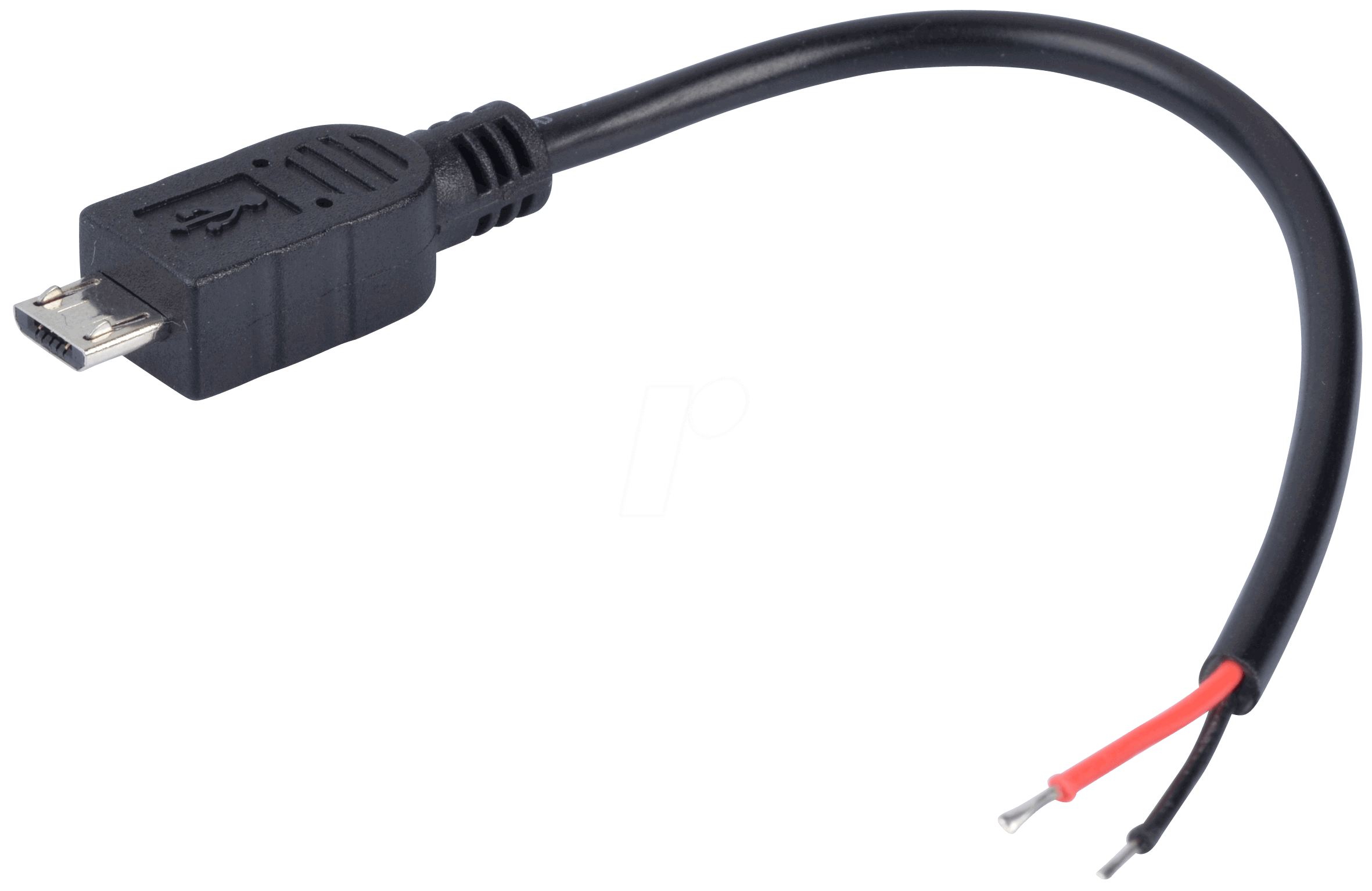
The Micro USB to 2-Pin Cable Connector is a versatile and commonly used electronic component that serves as a bridge between a micro USB power source and devices with a 2-pin interface. This cable is particularly useful for powering a wide range of electronic devices, such as development boards, small electronics projects, and battery chargers.
Explore Projects Built with Micro USB to Cable (2 Pin)
USB Type-C Powered LED Circuit with Resistor

This circuit consists of a USB Type-C port providing power to a red LED through a 1000 Ohm resistor. The resistor limits the current flowing through the LED, which lights up when the circuit is powered.
AC to DC Micro USB Power Supply with Buck Converter

This circuit is designed to convert AC power to regulated DC power. An AC source feeds a power transformer that steps down the voltage, which is then rectified by a bridge rectifier to produce a pulsating DC. This DC is further converted to a stable DC output by a step-down buck converter, which then provides power through a Micro USB connector.
Battery-Powered USB Charger with LED Indicator and DC Motor

This circuit converts AC power to DC using a bridge rectifier and regulates the voltage to 5V with a 7805 voltage regulator. It powers a USB port and indicates power status with an LED, while also providing a charging interface through a multi-charging cable.
USB-Powered Pushbutton Controlled LED Circuit

This circuit consists of a USB power converter supplying power to three pushbuttons, each connected to a corresponding red LED. When a button is pressed, it closes the circuit for its associated LED, causing the LED to light up. The common ground for the circuit is provided through a 40-pin connector, which also serves as an interface for the pushbuttons' inputs and the LEDs' cathodes.
Explore Projects Built with Micro USB to Cable (2 Pin)
USB Type-C Powered LED Circuit with Resistor
This circuit consists of a USB Type-C port providing power to a red LED through a 1000 Ohm resistor. The resistor limits the current flowing through the LED, which lights up when the circuit is powered.
AC to DC Micro USB Power Supply with Buck Converter
This circuit is designed to convert AC power to regulated DC power. An AC source feeds a power transformer that steps down the voltage, which is then rectified by a bridge rectifier to produce a pulsating DC. This DC is further converted to a stable DC output by a step-down buck converter, which then provides power through a Micro USB connector.
Battery-Powered USB Charger with LED Indicator and DC Motor
This circuit converts AC power to DC using a bridge rectifier and regulates the voltage to 5V with a 7805 voltage regulator. It powers a USB port and indicates power status with an LED, while also providing a charging interface through a multi-charging cable.
USB-Powered Pushbutton Controlled LED Circuit
This circuit consists of a USB power converter supplying power to three pushbuttons, each connected to a corresponding red LED. When a button is pressed, it closes the circuit for its associated LED, causing the LED to light up. The common ground for the circuit is provided through a 40-pin connector, which also serves as an interface for the pushbuttons' inputs and the LEDs' cathodes.
Common Applications and Use Cases
- Powering microcontroller boards (e.g., Arduino, Raspberry Pi)
- Charging battery-powered devices
- Providing power to custom electronics projects
- Connecting to breadboards for prototyping
Technical Specifications
Key Technical Details
- Voltage Rating: Typically 5V (from standard USB ports)
- Current Rating: Up to 2A (depending on cable gauge)
- Cable Length: Varies (common lengths include 0.5m, 1m, 2m)
- Micro USB Connector: USB 2.0 Micro-B male
- 2-Pin Connector: Generic 2-pin, pitch may vary
Pin Configuration and Descriptions
| Pin Number | Description | Notes |
|---|---|---|
| 1 | VCC (Power) | Connected to Micro USB VBUS pin |
| 2 | GND (Ground) | Connected to Micro USB GND pin |
Usage Instructions
How to Use the Component in a Circuit
- Connecting to a Power Source:
- Insert the Micro USB end of the cable into a compatible USB power adapter or USB port.
- Connecting to a Device:
- Connect the 2-pin end to the device's power input, ensuring correct polarity. The VCC and GND should match the device's power and ground pins.
Important Considerations and Best Practices
- Polarity: Always check the polarity of the 2-pin connector before connecting to your device. Reversing the polarity could damage the device.
- Power Rating: Do not exceed the current rating of the cable. Overloading the cable can cause overheating and potential failure.
- Cable Length: Be aware that longer cables can result in a voltage drop. Choose an appropriate cable length for your application.
- Connection Quality: Ensure that the connections are firm and secure to prevent intermittent power supply.
Troubleshooting and FAQs
Common Issues Users Might Face
- Device Not Powering On: Check the connections and ensure the USB power source is active.
- Intermittent Power: Inspect the cable for any physical damage or loose connections.
Solutions and Tips for Troubleshooting
- Polarity Check: Use a multimeter to verify the polarity of the 2-pin connector before connecting to your device.
- Power Source Verification: Confirm that the USB power source is supplying the correct voltage and current.
- Cable Inspection: Look for any signs of wear, tear, or damage to the cable. Replace if necessary.
FAQs
- Q: Can I use this cable to transfer data?
- A: No, this cable is designed for power connections only and does not support data transfer.
- Q: What should I do if the cable gets hot during use?
- A: Unplug the cable immediately and check if the current draw of your device is within the cable's rating. If the current draw is appropriate, the cable may be faulty.
Example Code for Arduino UNO
// This example demonstrates how to power an Arduino UNO using the Micro USB to 2-Pin Cable.
// No additional code is required for power connection.

void setup() {
  // Initialize digital pin LED_BUILTIN as an output.
  pinMode(LED_BUILTIN, OUTPUT);
}

void loop() {
  // Turn the LED on (HIGH is the voltage level)
  digitalWrite(LED_BUILTIN, HIGH);
  // Wait for a second
  delay(1000);
  // Turn the LED off by making the voltage LOW
  digitalWrite(LED_BUILTIN, LOW);
   // Wait for a second
  delay(1000);
}

// Note: The above code is for demonstration purposes only. The actual implementation
// may vary depending on the specific application and device requirements.
Note: The Arduino UNO can be powered through its 2-pin VIN and GND connections using the Micro USB to 2-Pin Cable, provided the power source is compatible with the Arduino's voltage and current requirements. Always refer to the Arduino UNO's specifications for proper power supply parameters.