The RC522 RFID Module, manufactured by NXP Semiconductors (Part ID: MFRC522), is a compact and cost-effective device designed for reading and writing RFID tags. Operating at a frequency of 13.56 MHz, it supports communication with a variety of RFID tags and cards. This module is widely used in applications such as access control, inventory management, contactless payment systems, and other identification-based systems.
Its small size, low power consumption, and compatibility with microcontrollers like Arduino make it a popular choice for hobbyists and professionals alike.
Explore Projects Built with RC522 RFID Module
Use Cirkit Designer to design, explore, and prototype these projects online. Some projects support real-time simulation. Click "Open Project" to start designing instantly!
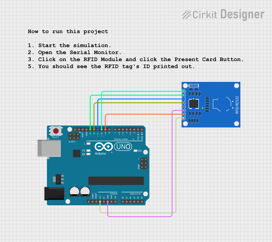
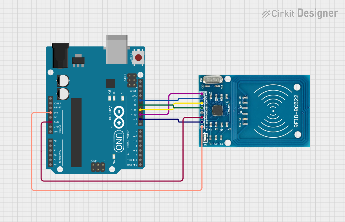
This circuit integrates an Arduino UNO with an RFID-RC522 module to enable RFID-based identification. The Arduino provides power and SPI communication to the RFID module, allowing it to read RFID tags and potentially perform actions based on the tag data.
This circuit integrates an Arduino UNO with an RC522 RFID module to create a system capable of reading RFID tags. The Arduino communicates with the RFID module via SPI, allowing it to initialize the module and read the unique identifiers of presented RFID cards, which are then printed to the serial monitor.
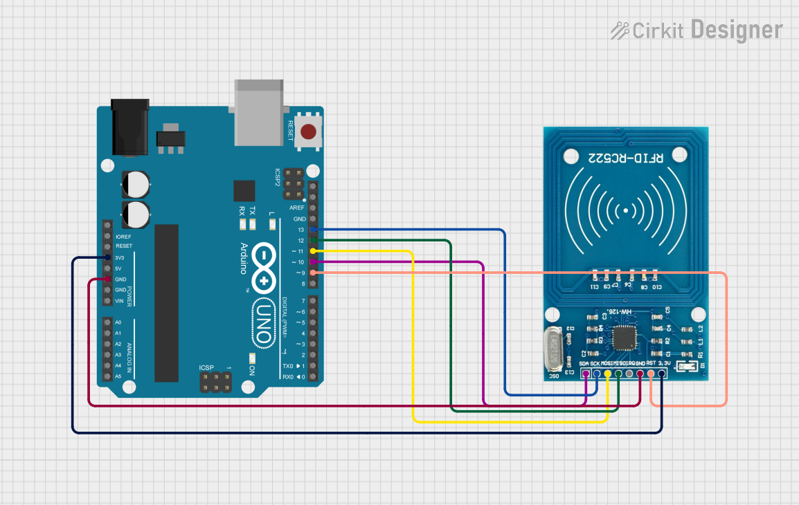
This circuit integrates an Arduino UNO with an RFID-RC522 module to enable RFID tag reading functionality. The Arduino provides power and SPI communication to the RFID module, allowing it to read and process RFID tags.
This circuit is designed to read RFID tags using the RFID-RC522 module, display information on an I2C LCD screen, and accept user input via a 4x4 membrane matrix keypad. It is controlled by an Arduino UNO, which is powered by a 3xAA battery pack, and communicates with the RFID module and LCD screen using SPI and I2C protocols, respectively.
Below are the key technical details and pin configuration of the RC522 RFID Module:
Key Technical Details
Parameter
Value
Operating Voltage
2.5V to 3.3V (logic level)
Power Supply Voltage
3.3V
Operating Current
13-26mA
Operating Frequency
13.56 MHz
Communication Protocol
SPI, I2C, UART
Maximum Data Rate
10 Mbps (SPI)
Reading Distance
Up to 5 cm
Dimensions
40mm x 60mm
Pin Configuration and Descriptions
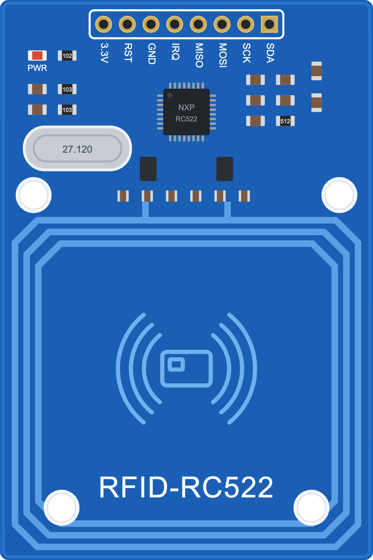
The RC522 RFID Module has 8 pins, as described in the table below:
Pin Name
Pin Number
Description
VCC
1
Power supply input (3.3V).
RST
2
Reset pin. Used to reset the module. Active LOW.
GND
3
Ground connection.
IRQ
4
Interrupt pin. Can be used to signal events to the microcontroller.
MISO
5
Master-In-Slave-Out (SPI data output).
MOSI
6
Master-Out-Slave-In (SPI data input).
SCK
7
Serial Clock (SPI clock input).
SDA/SS
8
Slave Select (SPI chip select). Also used for I2C communication.
Usage Instructions
How to Use the RC522 RFID Module in a Circuit
Power the Module: Connect the VCC pin to a 3.3V power source and the GND pin to ground.
Connect to a Microcontroller: Use the SPI interface to connect the module to a microcontroller (e.g., Arduino UNO). The typical connections are:
MISO to Arduino pin 12
MOSI to Arduino pin 11
SCK to Arduino pin 13
SDA/SS to Arduino pin 10
RST to Arduino pin 9
Install Required Libraries: For Arduino, install the "MFRC522" library from the Arduino IDE Library Manager.
Write Code: Use the library functions to initialize the module, read RFID tags, and write data to them.
Important Considerations and Best Practices
Ensure the module is powered with 3.3V. Using 5V may damage the module.
Keep the RFID tag within 5 cm of the module for reliable reading and writing.
Avoid placing metal objects near the module, as they can interfere with the RFID signal.
Use proper pull-up resistors if required for I2C communication.
Example Code for Arduino UNO
Below is an example Arduino sketch to read an RFID tag using the RC522 module:
#include <SPI.h>
#include <MFRC522.h>

// Define RC522 module pins
#define RST_PIN 9  // Reset pin connected to Arduino pin 9
#define SS_PIN 10  // Slave Select pin connected to Arduino pin 10

MFRC522 rfid(SS_PIN, RST_PIN); // Create an instance of the MFRC522 class

void setup() {
  Serial.begin(9600); // Initialize serial communication
  SPI.begin();        // Initialize SPI bus
  rfid.PCD_Init();    // Initialize the RC522 module
  Serial.println("Place an RFID tag near the reader...");
}

void loop() {
  // Check if an RFID tag is present
  if (!rfid.PICC_IsNewCardPresent() || !rfid.PICC_ReadCardSerial()) {
    return; // Exit if no tag is detected
  }

  // Print the UID of the detected tag
  Serial.print("Tag UID: ");
  for (byte i = 0; i < rfid.uid.size; i++) {
    Serial.print(rfid.uid.uidByte[i], HEX); // Print each byte of the UID in HEX
    Serial.print(" ");
  }
  Serial.println();

  // Halt the tag to stop further communication
  rfid.PICC_HaltA();
}
Troubleshooting and FAQs
Common Issues and Solutions
Module Not Responding
Cause: Incorrect wiring or power supply.
Solution: Double-check all connections and ensure the module is powered with 3.3V.
Unable to Read RFID Tags
Cause: Tag is out of range or incompatible.
Solution: Ensure the tag is within 5 cm of the module and operates at 13.56 MHz.
Interference from Metal Objects
Cause: Metal objects near the module can block or distort the RFID signal.
Solution: Remove any metal objects near the module.
Library Not Found
Cause: Required library is not installed in the Arduino IDE.
Solution: Install the "MFRC522" library from the Library Manager.
FAQs
Can the RC522 module write data to RFID tags?
Yes, the module supports both reading and writing to compatible RFID tags.
What is the maximum range of the RC522 module?
The module can read tags up to a distance of 5 cm under optimal conditions.
Can the RC522 module work with 5V logic?
No, the module operates at 3.3V logic. Use a level shifter if connecting to a 5V microcontroller.
What types of RFID tags are compatible with the RC522 module?
The module is compatible with ISO/IEC 14443 Type A and Type B tags, such as MIFARE cards.

 Open Project in Cirkit Designer