How to Use JST PH 2.0 connector: Examples, Pinouts, and Specs
Introduction
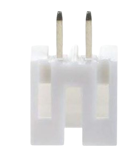
The JST PH 2.0 connector is a compact, versatile electrical connector widely used in various electronic applications. It is part of the JST PH series, known for its 2.0mm pitch, which refers to the distance between the centers of adjacent pins. This connector is designed for secure wire-to-board or wire-to-wire connections, making it suitable for low to moderate power and signal applications. Common use cases include battery connections in portable devices, signal transfer in consumer electronics, and power supply connections in industrial equipment.
Explore Projects Built with JST PH 2.0 connector
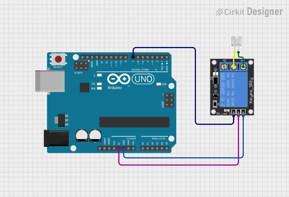
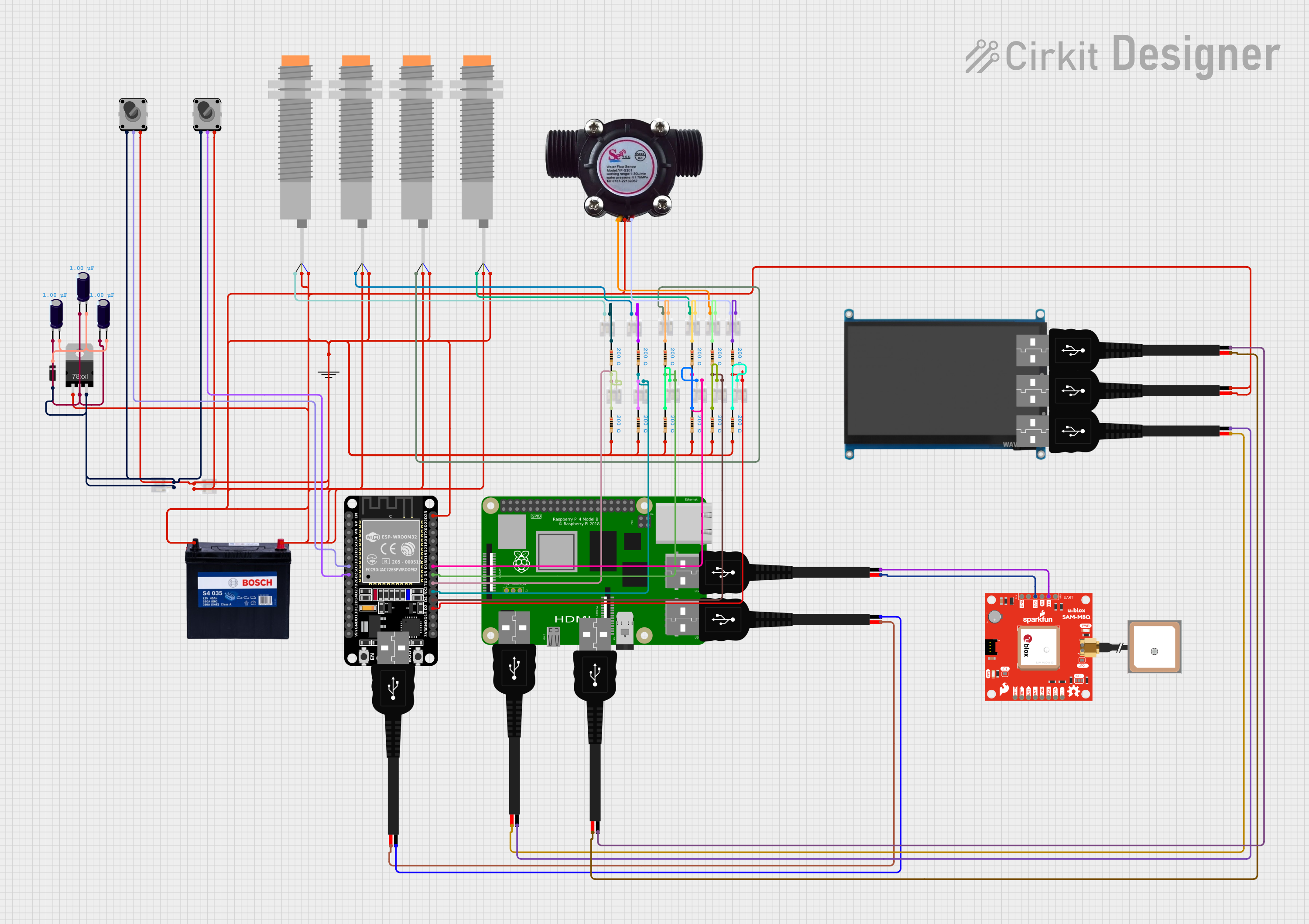


Explore Projects Built with JST PH 2.0 connector
Technical Specifications
General Characteristics
- Pitch: 2.0mm
- Current Rating: Typically 2A (may vary by specific model)
- Voltage Rating: Typically 100V (may vary by specific model)
- Temperature Range: -25°C to +85°C (operating)
Pin Configuration and Descriptions
The JST PH 2.0 connector series includes a variety of pin counts. Below is a table for a common 4-pin configuration:
| Pin Number | Description |
|---|---|
| 1 | Power (+) |
| 2 | Data/Signal Line 1 |
| 3 | Data/Signal Line 2 |
| 4 | Ground (-) |
Note: The actual pinout may vary depending on the specific application and design requirements.
Usage Instructions
Integration into a Circuit
- Wire Preparation: Strip the end of the wires to expose the appropriate length of conductor for insertion into the crimp terminals.
- Crimping: Use a crimping tool designed for JST PH terminals to crimp the exposed wire to the terminal. Ensure a secure and gas-tight crimp.
- Insertion: Insert the crimped terminals into the housing, ensuring they are fully seated and locked in place.
- Mating: Align the male and female connectors and gently press them together until they click, indicating a secure connection.
Best Practices
- Polarization: The JST PH connector is polarized to prevent incorrect mating. Always observe the correct orientation.
- Cable Strain Relief: Provide strain relief to prevent stress on the wire-to-terminal connection.
- Inspection: After assembly, inspect the connector for any signs of damage or incomplete mating.
- Unmating: When disconnecting, pull on the connector housing rather than the wires to avoid damage.
Troubleshooting and FAQs
Common Issues
- Intermittent Connection: Check for loose terminals within the housing or damaged wires.
- Difficulty Mating: Ensure the connector is correctly oriented and that no foreign objects are obstructing the connection.
- Overheating: Verify that the current and voltage do not exceed the connector's ratings.
FAQs
Q: Can I reuse a JST PH connector after it has been disconnected? A: Yes, JST PH connectors are designed for multiple mating cycles. However, if there is any sign of wear or damage, it is recommended to replace the connector.
Q: How do I know if the terminal is fully seated in the housing? A: A properly seated terminal will often emit a 'click' sound, and there should be no metal exposed at the back of the connector housing.
Q: What should I do if the connector does not fit into the board header? A: Double-check the pitch of the board header and the connector to ensure they match. If they do, inspect for any misalignment or debris and try again.
For any further assistance or detailed product inquiries, please contact the manufacturer or your local distributor.
Note: This documentation is provided for informational purposes only and does not constitute professional engineering advice. Always consult a qualified engineer or technician when working with electronic components.