How to Use Lm317: Examples, Pinouts, and Specs
Introduction
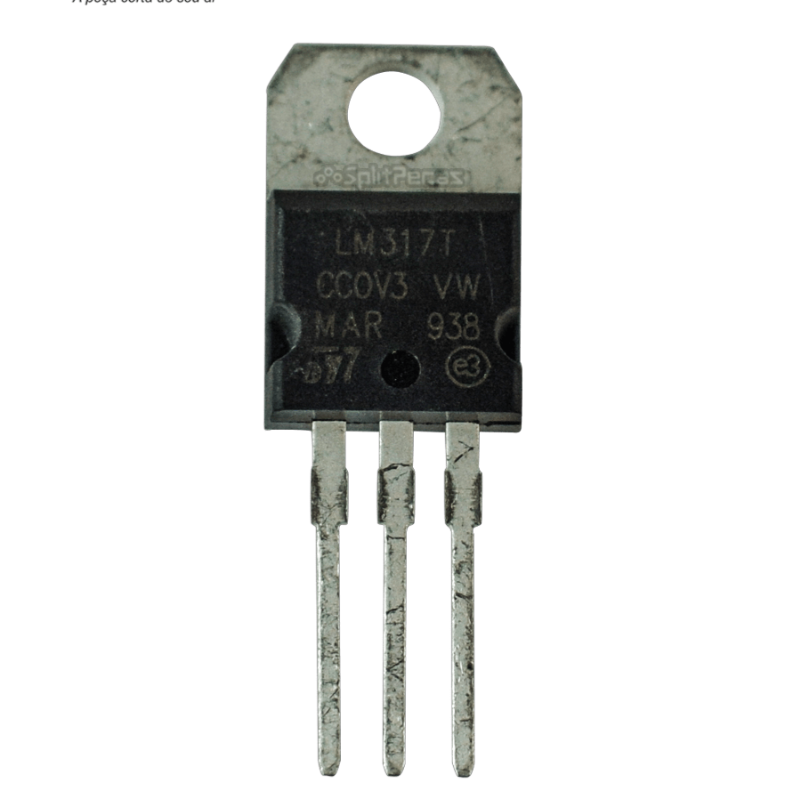
The LM317 is an adjustable voltage regulator that can output a range of voltages from 1.25V to 37V with a maximum output current of 1.5A. It is commonly used in power supply circuits to provide a stable and adjustable output voltage. The LM317 is versatile and can be used in various applications, including battery chargers, adjustable power supplies, and current regulators.
Explore Projects Built with Lm317
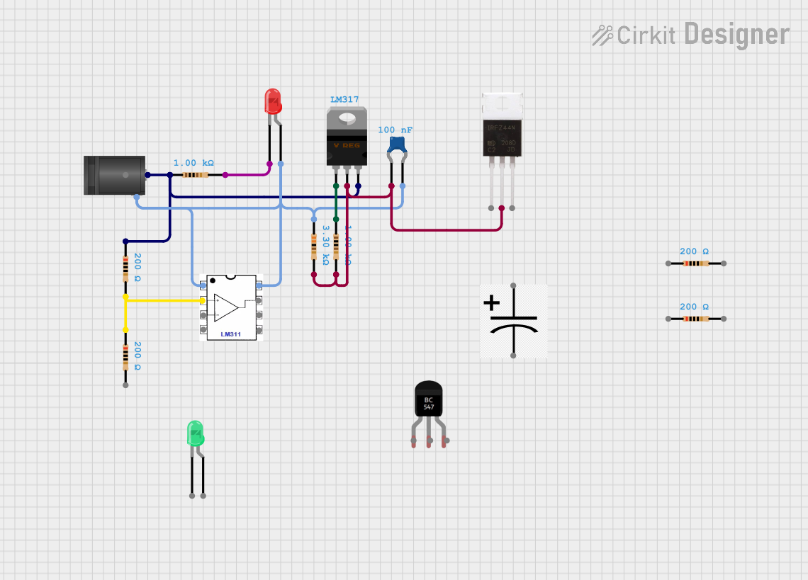
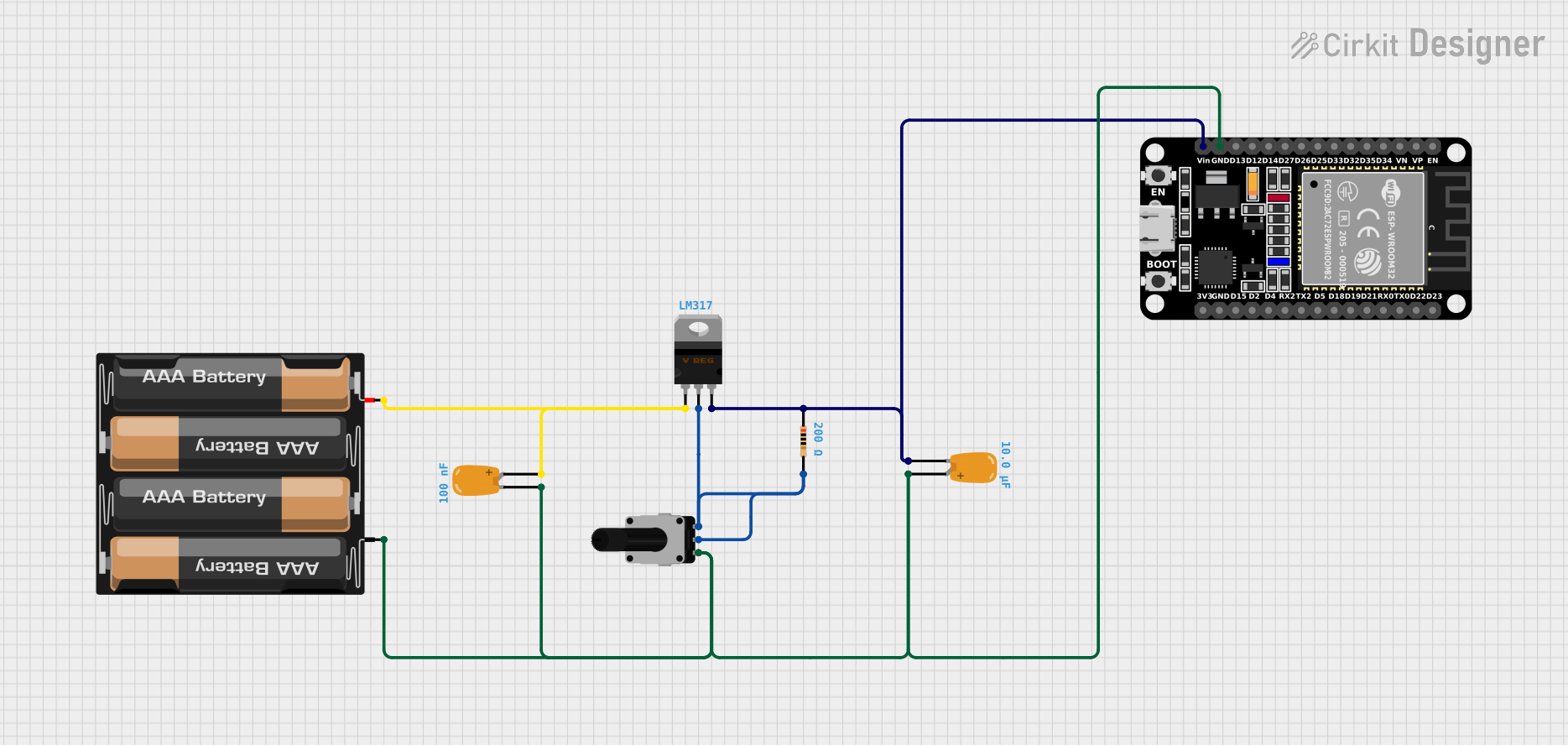
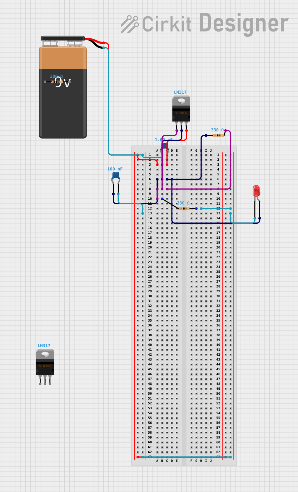
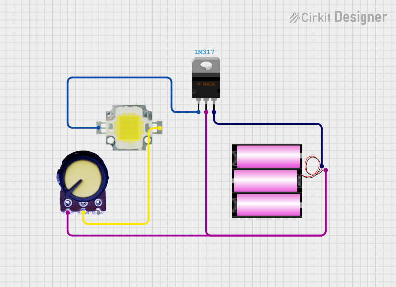
Explore Projects Built with Lm317
Technical Specifications
Key Technical Details
| Parameter | Value |
|---|---|
| Output Voltage Range | 1.25V to 37V |
| Maximum Output Current | 1.5A |
| Input Voltage Range | 3V to 40V |
| Line Regulation | 0.01%/V |
| Load Regulation | 0.1% |
| Temperature Range | 0°C to 125°C |
Pin Configuration and Descriptions
| Pin Number | Pin Name | Description |
|---|---|---|
| 1 | Adjust | Adjusts the output voltage |
| 2 | Output | Regulated output voltage |
| 3 | Input | Unregulated input voltage |
Usage Instructions
How to Use the LM317 in a Circuit
To use the LM317 in a circuit, follow these steps:
Connect the Input Voltage:
- Connect the unregulated input voltage to the Input pin (Pin 3).
Set the Output Voltage:
- Use a voltage divider network with resistors ( R1 ) and ( R2 ) to set the desired output voltage. The output voltage ( V_{out} ) can be calculated using the formula: [ V_{out} = V_{ref} \left(1 + \frac{R2}{R1}\right) + I_{adj} \cdot R2 ] where ( V_{ref} ) is typically 1.25V and ( I_{adj} ) is the adjustment pin current (usually negligible).
Connect the Output Load:
- Connect the load to the Output pin (Pin 2).
Important Considerations and Best Practices
Heat Dissipation:
- The LM317 can dissipate significant power, especially at higher currents and voltage drops. Use a heatsink to prevent overheating.
Capacitors:
- Place a 0.1µF capacitor between the Input pin and ground to improve stability.
- Place a 1µF capacitor between the Output pin and ground to improve transient response.
Protection Diodes:
- Use protection diodes if the output voltage can exceed the input voltage, such as in battery charging applications.
Example Circuit
Below is an example circuit diagram for using the LM317 to provide a 5V output from a 12V input:
   +12V
     |
     |
    [ ] R1 = 240Ω
     |
     +-----> Adjust (Pin 1)
     |
    [ ] R2 = 720Ω
     |
     +-----> Output (Pin 2) -----> +5V
     |
    [ ]
     |
    GND
Troubleshooting and FAQs
Common Issues and Solutions
Output Voltage Not Stable:
- Ensure that the input voltage is at least 3V higher than the desired output voltage.
- Check the connections and ensure that the resistors ( R1 ) and ( R2 ) are correctly placed.
Overheating:
- Use a heatsink to dissipate excess heat.
- Ensure that the load current does not exceed 1.5A.
No Output Voltage:
- Verify that the input voltage is correctly applied.
- Check for short circuits or incorrect connections.
FAQs
Q: Can the LM317 be used to regulate current? A: Yes, the LM317 can be configured as a current regulator by placing a resistor between the output and adjust pins.
Q: What is the minimum input voltage for the LM317? A: The minimum input voltage is 3V above the desired output voltage.
Q: How do I improve the transient response of the LM317? A: Place a 1µF capacitor between the output pin and ground.
Arduino Example Code
Here is an example of how to use the LM317 with an Arduino UNO to monitor the output voltage:
// Define the analog pin for voltage measurement
const int voltagePin = A0;

void setup() {
  // Initialize serial communication
  Serial.begin(9600);
}

void loop() {
  // Read the analog value from the voltage pin
  int sensorValue = analogRead(voltagePin);

  // Convert the analog value to voltage
  float voltage = sensorValue * (5.0 / 1023.0);

  // Print the voltage to the serial monitor
  Serial.print("Voltage: ");
  Serial.print(voltage);
  Serial.println(" V");

  // Wait for a second before the next reading
  delay(1000);
}
This code reads the output voltage of the LM317 and prints it to the serial monitor. Connect the output of the LM317 to the analog pin A0 of the Arduino UNO.
This documentation provides a comprehensive guide to using the LM317 adjustable voltage regulator. Whether you are a beginner or an experienced user, this guide will help you effectively utilize the LM317 in your projects.