Cirkit Designer Logo
Cirkit Designer
Your all-in-one circuit design IDE
Home / 
Component Documentation

How to Use MCP3421 18-Bit ADC: Examples, Pinouts, and Specs

Image of MCP3421 18-Bit ADC
Cirkit Designer LogoDesign with MCP3421 18-Bit ADC in Cirkit Designer

Introduction

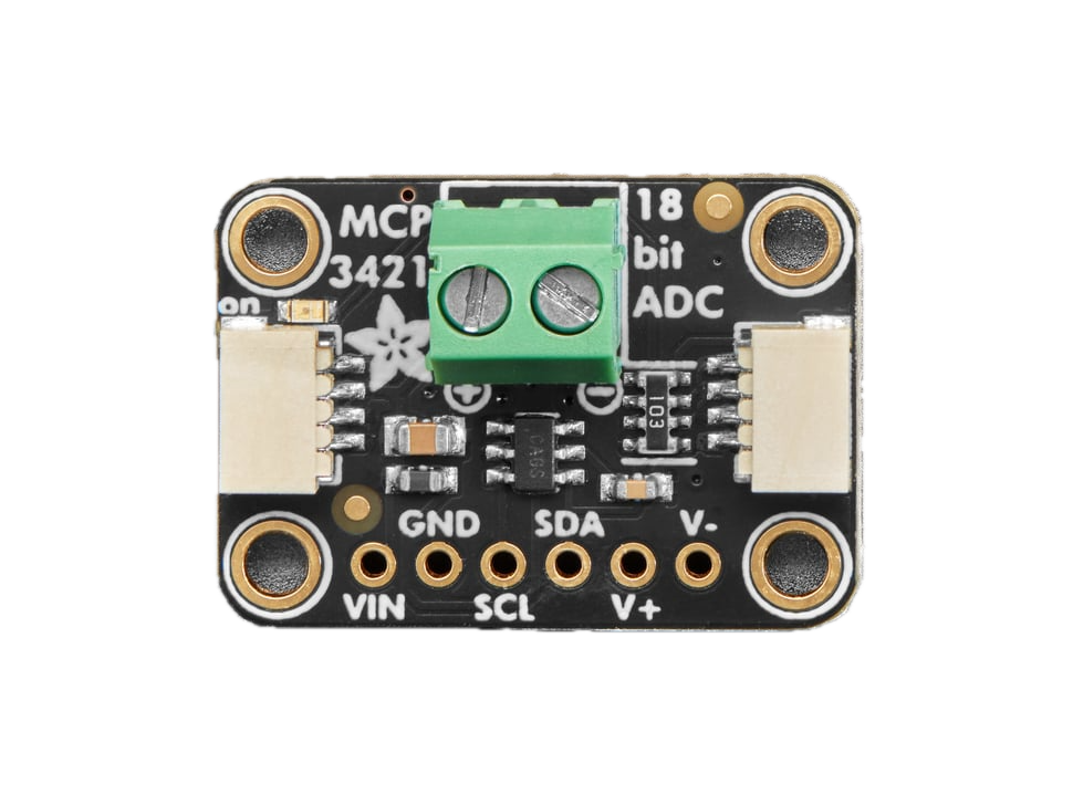
The MCP3421, manufactured by Adafruit (Part ID: 5870), is a high-resolution, 1-channel, 18-bit analog-to-digital converter (ADC) with an integrated programmable gain amplifier (PGA). It operates over an I2C interface, making it easy to integrate into microcontroller-based systems. Designed for low-power applications, the MCP3421 is ideal for battery-operated devices and precision measurement tasks.

Explore Projects Built with MCP3421 18-Bit ADC

Use Cirkit Designer to design, explore, and prototype these projects online. Some projects support real-time simulation. Click "Open Project" to start designing instantly!
MCP23017-Expanded I/O Interface with ADS1115 ADC and ESP32 Control
Image of door and window sensors: A project utilizing MCP3421 18-Bit ADC in a practical application
This circuit features two MCP23017 I/O expanders interfaced with multiple switches, allowing for the expansion of input capabilities. The MCP23017s are connected via I2C to an Olimex ESP32-EVB microcontroller, which likely manages the input states from the switches. Additionally, an Adafruit ADS1115 16-bit ADC is included, suggesting that some analog inputs are being monitored, with the ADC also interfaced with the ESP32 via I2C.
Cirkit Designer LogoOpen Project in Cirkit Designer
I2C-Controlled Relay Switching with ESP32 and MCP23017 for Home Automation
Image of Vloerverwarming: A project utilizing MCP3421 18-Bit ADC in a practical application
This circuit appears to be a control system utilizing two MCP23017 I/O expanders interfaced with an Olimex ESP32-EVB microcontroller via I2C communication, as indicated by the SDA and SCL connections with pull-up resistors. The MCP23017 expanders control an 8-channel relay module, allowing the microcontroller to switch various loads, potentially for home automation or industrial control. Additionally, there is an Adafruit ADS1115 16-bit ADC for analog signal measurement, and several heating actuators and a thermostat are connected, suggesting temperature control functionality.
Cirkit Designer LogoOpen Project in Cirkit Designer
Xiao ESP32 C3 and ADS1115-Based Light Intensity Data Logger
Image of Thesis Project: A project utilizing MCP3421 18-Bit ADC in a practical application
This circuit features a Xiao ESP32 C3 microcontroller interfaced with an Adafruit ADS1115 16-bit ADC via I2C for reading analog signals from a phototransistor. The phototransistor's output is conditioned by a resistor and fed into the ADC, which converts the light intensity into a digital signal. The ESP32 C3 reads the ADC values and outputs the readings to the serial monitor, allowing for light intensity monitoring.
Cirkit Designer LogoOpen Project in Cirkit Designer
Arduino UNO and Adafruit ADS1015 Based Analog to Digital Conversion
Image of relan: A project utilizing MCP3421 18-Bit ADC in a practical application
This circuit is designed to measure analog voltage levels using a potentiometer and convert them to digital values with an Adafruit ADS1015 12Bit I2C ADC. The Arduino UNO serves as the controller, reading the ADC values via I2C communication and outputting the results to the serial monitor. A 9V battery powers the circuit, and a resistor is used to connect the potentiometer's output to the ADC's analog input channel AIN0.
Cirkit Designer LogoOpen Project in Cirkit Designer

Explore Projects Built with MCP3421 18-Bit ADC

Use Cirkit Designer to design, explore, and prototype these projects online. Some projects support real-time simulation. Click "Open Project" to start designing instantly!
Image of door and window sensors: A project utilizing MCP3421 18-Bit ADC in a practical application
MCP23017-Expanded I/O Interface with ADS1115 ADC and ESP32 Control
This circuit features two MCP23017 I/O expanders interfaced with multiple switches, allowing for the expansion of input capabilities. The MCP23017s are connected via I2C to an Olimex ESP32-EVB microcontroller, which likely manages the input states from the switches. Additionally, an Adafruit ADS1115 16-bit ADC is included, suggesting that some analog inputs are being monitored, with the ADC also interfaced with the ESP32 via I2C.
Cirkit Designer LogoOpen Project in Cirkit Designer
Image of Vloerverwarming: A project utilizing MCP3421 18-Bit ADC in a practical application
I2C-Controlled Relay Switching with ESP32 and MCP23017 for Home Automation
This circuit appears to be a control system utilizing two MCP23017 I/O expanders interfaced with an Olimex ESP32-EVB microcontroller via I2C communication, as indicated by the SDA and SCL connections with pull-up resistors. The MCP23017 expanders control an 8-channel relay module, allowing the microcontroller to switch various loads, potentially for home automation or industrial control. Additionally, there is an Adafruit ADS1115 16-bit ADC for analog signal measurement, and several heating actuators and a thermostat are connected, suggesting temperature control functionality.
Cirkit Designer LogoOpen Project in Cirkit Designer
Image of Thesis Project: A project utilizing MCP3421 18-Bit ADC in a practical application
Xiao ESP32 C3 and ADS1115-Based Light Intensity Data Logger
This circuit features a Xiao ESP32 C3 microcontroller interfaced with an Adafruit ADS1115 16-bit ADC via I2C for reading analog signals from a phototransistor. The phototransistor's output is conditioned by a resistor and fed into the ADC, which converts the light intensity into a digital signal. The ESP32 C3 reads the ADC values and outputs the readings to the serial monitor, allowing for light intensity monitoring.
Cirkit Designer LogoOpen Project in Cirkit Designer
Image of relan: A project utilizing MCP3421 18-Bit ADC in a practical application
Arduino UNO and Adafruit ADS1015 Based Analog to Digital Conversion
This circuit is designed to measure analog voltage levels using a potentiometer and convert them to digital values with an Adafruit ADS1015 12Bit I2C ADC. The Arduino UNO serves as the controller, reading the ADC values via I2C communication and outputting the results to the serial monitor. A 9V battery powers the circuit, and a resistor is used to connect the potentiometer's output to the ADC's analog input channel AIN0.
Cirkit Designer LogoOpen Project in Cirkit Designer

Common Applications and Use Cases

  • Sensor data acquisition (e.g., temperature, pressure, or light sensors)
  • Battery monitoring systems
  • Portable medical devices
  • Industrial process control
  • Precision instrumentation

Technical Specifications

The MCP3421 offers a combination of high resolution, low power consumption, and flexible gain settings. Below are its key technical details:

Parameter Value
Resolution 18 bits
Number of Channels 1
Interface I2C
Input Voltage Range 0V to VREF (typically 2.048V)
Programmable Gain Amplifier 1x, 2x, 4x, 8x
Supply Voltage 2.7V to 5.5V
Typical Supply Current 145 µA (active mode), 0.1 µA (standby mode)
Conversion Speed 3.75 SPS to 240 SPS (selectable)
Operating Temperature Range -40°C to +125°C

Pin Configuration and Descriptions

The MCP3421 is available in an 8-pin package. Below is the pinout and description:

Pin Name Description
1 VDD Power supply input (2.7V to 5.5V)
2 SCL I2C clock line
3 SDA I2C data line
4 ADDR I2C address selection pin (connect to GND or VDD to set address)
5 NC No connection (leave unconnected)
6 NC No connection (leave unconnected)
7 VSS Ground (0V reference)
8 VIN+ Positive analog input

Usage Instructions

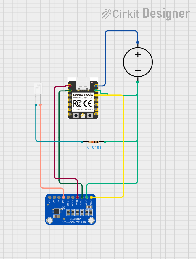
How to Use the MCP3421 in a Circuit

  1. Power Supply: Connect the VDD pin to a 2.7V–5.5V power source and the VSS pin to ground.
  2. Analog Input: Connect the analog signal to the VIN+ pin. Ensure the input voltage does not exceed the reference voltage (typically 2.048V).
  3. I2C Interface:
    • Connect the SCL and SDA pins to the corresponding I2C lines of your microcontroller.
    • Use pull-up resistors (typically 4.7 kΩ) on the SCL and SDA lines.
  4. Address Selection: Use the ADDR pin to set the I2C address:
    • Connect to GND for address 0x68.
    • Connect to VDD for address 0x69.

Important Considerations and Best Practices

  • Input Voltage Range: Ensure the input voltage does not exceed the reference voltage to avoid damage or inaccurate readings.
  • Bypass Capacitor: Place a 0.1 µF ceramic capacitor close to the VDD pin for power supply decoupling.
  • I2C Pull-Up Resistors: Use appropriate pull-up resistors on the I2C lines to ensure reliable communication.
  • Gain Settings: Select the appropriate PGA gain (1x, 2x, 4x, or 8x) based on the input signal amplitude for optimal resolution.

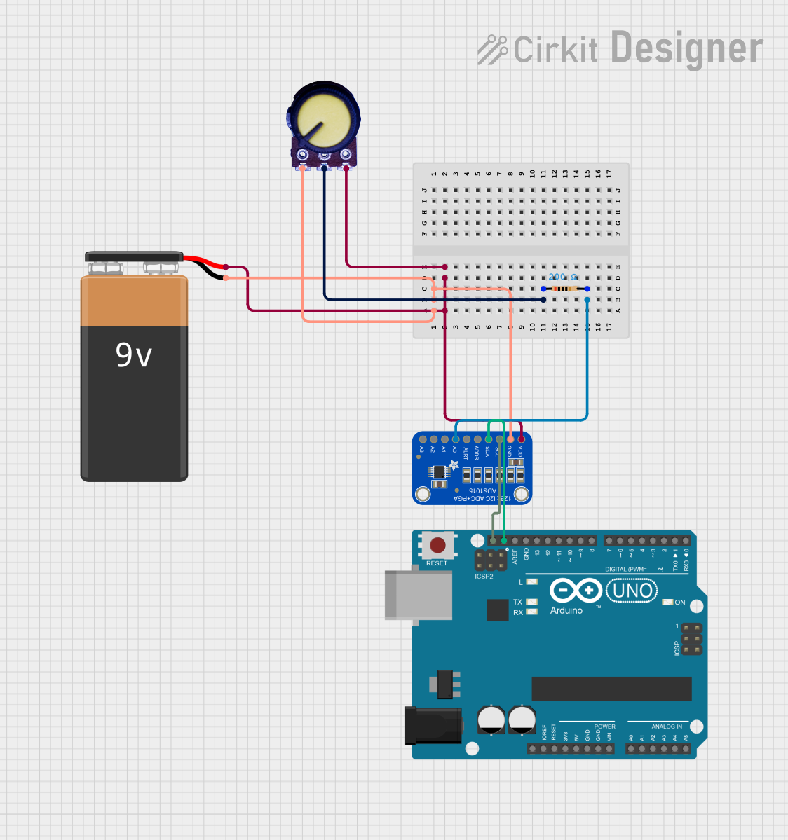
Example Code for Arduino UNO

Below is an example of how to interface the MCP3421 with an Arduino UNO using the Wire library:

#include <Wire.h>

#define MCP3421_ADDRESS 0x68 // Default I2C address when ADDR is connected to GND

void setup() {
  Wire.begin(); // Initialize I2C communication
  Serial.begin(9600); // Initialize serial communication for debugging
}

void loop() {
  Wire.beginTransmission(MCP3421_ADDRESS);
  Wire.write(0x10); // Configuration byte: 18-bit resolution, 1x gain, continuous mode
  Wire.endTransmission();

  delay(500); // Wait for conversion to complete

  Wire.requestFrom(MCP3421_ADDRESS, 3); // Request 3 bytes (18-bit data + status)
  if (Wire.available() == 3) {
    uint32_t rawData = 0;
    rawData |= Wire.read() << 16; // MSB
    rawData |= Wire.read() << 8;  // Middle byte
    rawData |= Wire.read();       // LSB and status

    // Extract the 18-bit ADC value (ignore the last 4 status bits)
    int32_t adcValue = rawData >> 4;

    // Convert to voltage (assuming 2.048V reference and 1x gain)
    float voltage = (adcValue * 2.048) / 262144.0;

    Serial.print("ADC Value: ");
    Serial.print(adcValue);
    Serial.print(" | Voltage: ");
    Serial.print(voltage, 6);
    Serial.println(" V");
  }

  delay(1000); // Wait before the next reading
}

Troubleshooting and FAQs

Common Issues and Solutions

  1. No I2C Communication:

    • Ensure the SCL and SDA lines have proper pull-up resistors (4.7 kΩ recommended).
    • Verify the I2C address matches the configuration of the ADDR pin.
    • Check for loose or incorrect wiring.
  2. Incorrect ADC Readings:

    • Ensure the input voltage does not exceed the reference voltage.
    • Verify the PGA gain setting is appropriate for the input signal amplitude.
    • Check for noise or instability in the power supply.
  3. Device Not Detected on I2C Bus:

    • Use an I2C scanner sketch to confirm the MCP3421's address.
    • Ensure the ADDR pin is correctly connected to GND or VDD.

FAQs

Q: Can I use a different reference voltage?
A: No, the MCP3421 has an internal reference voltage of 2.048V. External reference voltage is not supported.

Q: What is the maximum sampling rate?
A: The maximum sampling rate is 240 samples per second (SPS) at 12-bit resolution. At 18-bit resolution, the sampling rate is 3.75 SPS.

Q: Can I connect multiple MCP3421 devices on the same I2C bus?
A: Yes, you can connect up to two MCP3421 devices by configuring the ADDR pin to different states (GND or VDD) to assign unique I2C addresses.