How to Use Dfrobot turbidity sensor: Examples, Pinouts, and Specs
Introduction
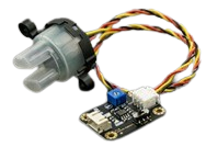
The DFRobot Turbidity Sensor is a device designed to measure the turbidity of water, which is an indicator of the presence of suspended particles. It provides an analog voltage output proportional to the turbidity level, making it an essential tool for water quality monitoring applications. This sensor is widely used in environmental monitoring, aquariums, water treatment systems, and laboratory experiments.
By integrating this sensor into a circuit, users can detect changes in water clarity and quantify the concentration of suspended particles, enabling real-time monitoring and analysis.
Explore Projects Built with Dfrobot turbidity sensor
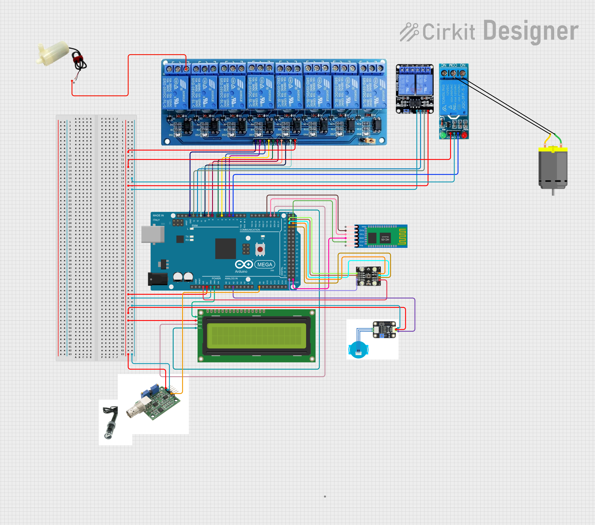
Explore Projects Built with Dfrobot turbidity sensor
Technical Specifications
Below are the key technical details and pin configuration of the DFRobot Turbidity Sensor:
Key Technical Details
| Parameter | Value |
|---|---|
| Operating Voltage | 5V DC |
| Output Signal | Analog Voltage (0-4.5V) |
| Measurement Range | 0 to 1000 NTU (Nephelometric Turbidity Units) |
| Operating Temperature | -30°C to 80°C |
| Response Time | < 500ms |
| Cable Length | 1 meter |
| Dimensions | 60mm x 20mm x 20mm |
Pin Configuration
| Pin Name | Description |
|---|---|
| VCC | Power supply input (5V DC) |
| GND | Ground |
| AOUT | Analog output signal proportional to turbidity |
Usage Instructions
How to Use the Sensor in a Circuit
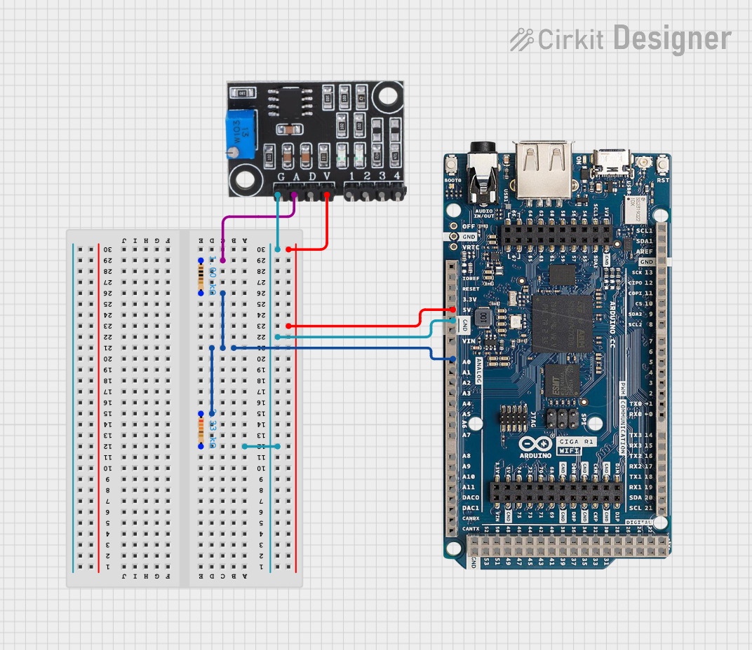
Wiring the Sensor:
- Connect the
VCCpin of the sensor to the 5V pin of your microcontroller or power source. - Connect the
GNDpin to the ground (GND) of your circuit. - Connect the
AOUTpin to an analog input pin of your microcontroller (e.g., Arduino).
- Connect the
Calibrating the Sensor:
- Place the sensor in clean water to measure the baseline voltage for clear water.
- Use a known turbidity standard (e.g., a solution with a specific NTU value) to calibrate the sensor for accurate measurements.
Reading the Output:
- The sensor outputs an analog voltage that corresponds to the turbidity level. Higher turbidity results in a lower voltage, while lower turbidity results in a higher voltage.
Important Considerations and Best Practices
- Avoid Air Bubbles: Ensure there are no air bubbles around the sensor probe, as they can affect the accuracy of the readings.
- Keep the Sensor Clean: Regularly clean the sensor to prevent fouling or buildup of debris, which can interfere with measurements.
- Stable Power Supply: Use a stable 5V power source to avoid fluctuations in the output signal.
- Temperature Effects: While the sensor operates over a wide temperature range, extreme temperature changes can slightly affect readings. Consider compensating for temperature if high precision is required.
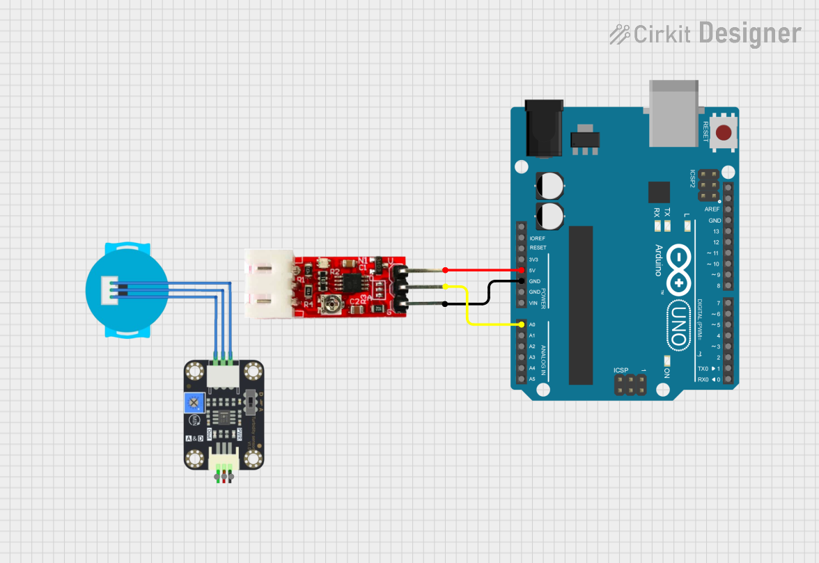
Example Code for Arduino UNO
Below is an example of how to use the DFRobot Turbidity Sensor with an Arduino UNO:
// DFRobot Turbidity Sensor Example Code
// This code reads the analog output from the turbidity sensor and converts it
// into a voltage value. The voltage can then be used to estimate turbidity.

const int sensorPin = A0; // Connect the AOUT pin of the sensor to A0
float sensorVoltage = 0;  // Variable to store the sensor voltage
int sensorValue = 0;      // Variable to store the raw analog reading

void setup() {
  Serial.begin(9600); // Initialize serial communication at 9600 baud
  pinMode(sensorPin, INPUT); // Set the sensor pin as an input
}

void loop() {
  // Read the raw analog value from the sensor
  sensorValue = analogRead(sensorPin);

  // Convert the raw value (0-1023) to a voltage (0-5V)
  sensorVoltage = sensorValue * (5.0 / 1023.0);

  // Print the voltage to the Serial Monitor
  Serial.print("Sensor Voltage: ");
  Serial.print(sensorVoltage);
  Serial.println(" V");

  // Add a delay for stability
  delay(1000); // Wait for 1 second before the next reading
}
Troubleshooting and FAQs
Common Issues and Solutions
No Output Signal:
- Cause: Incorrect wiring or loose connections.
- Solution: Double-check the wiring and ensure all connections are secure.
Inconsistent Readings:
- Cause: Air bubbles or debris on the sensor.
- Solution: Remove air bubbles and clean the sensor probe.
Output Voltage Stuck at Maximum or Minimum:
- Cause: Sensor may be damaged or submerged in an inappropriate medium.
- Solution: Verify the sensor's condition and ensure it is used in water.
Readings Drift Over Time:
- Cause: Sensor fouling or power supply instability.
- Solution: Clean the sensor regularly and use a stable power source.
FAQs
Q: Can this sensor be used in saltwater?
A: Yes, the sensor can be used in saltwater, but regular cleaning is recommended to prevent corrosion or buildup.
Q: How do I convert the voltage output to NTU?
A: The relationship between voltage and NTU depends on calibration. Use a known turbidity standard to create a conversion formula specific to your setup.
Q: Can I use this sensor with a 3.3V microcontroller?
A: The sensor is designed for 5V operation. If using a 3.3V microcontroller, a level shifter or voltage divider may be required for compatibility.
Q: What is the maximum depth the sensor can be submerged?
A: The sensor is designed for shallow water applications. Avoid submerging it beyond the cable's length or exposing it to high water pressure.