How to Use ZS-042 RTC Modulea: Examples, Pinouts, and Specs
Introduction
The ZS-042 RTC Module is a Real-Time Clock (RTC) module that provides precise timekeeping when embedded in electronic projects. It is based on the DS3231 integrated circuit, which is known for its high accuracy and stability due to its temperature-compensated crystal oscillator. This module is commonly used in applications such as data loggers, alarms, time-stamping events, and digital clocks.
Explore Projects Built with ZS-042 RTC Modulea
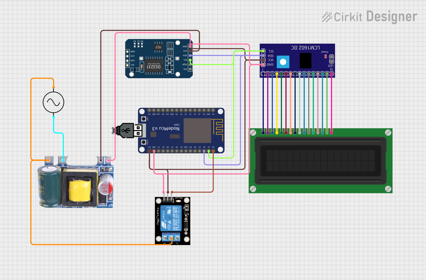
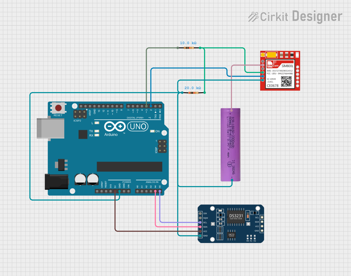


Explore Projects Built with ZS-042 RTC Modulea
Common Applications and Use Cases
- Data logging with time stamps
- Alarm clocks and wake-up devices
- Timekeeping for embedded systems
- Synchronization of events in electronic systems
Technical Specifications
Key Technical Details
- Timekeeping Accuracy: ±2ppm from 0°C to +40°C
- Battery Backup: CR2032 coin cell battery
- Communication: I2C interface
- Operating Voltage: 3.3V to 5.5V
- Operating Temperature: -40°C to +85°C
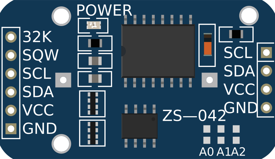
Pin Configuration and Descriptions
| Pin Number | Pin Name | Description |
|---|---|---|
| 1 | VCC | Power supply (3.3V to 5.5V) |
| 2 | GND | Ground |
| 3 | SDA | Serial Data Line for I2C communication |
| 4 | SCL | Serial Clock Line for I2C communication |
| 5 | SQW | Square Wave/Interrupt Output |
| 6 | 32K | 32KHz Output |
Usage Instructions
How to Use the Component in a Circuit
- Powering the Module: Connect the VCC pin to a 3.3V or 5V power supply and the GND pin to the ground of your system.
- I2C Communication: Connect the SDA and SCL pins to the corresponding SDA and SCL pins on your microcontroller (e.g., Arduino UNO).
- Battery Backup: Insert a CR2032 coin cell battery into the battery holder to enable timekeeping even when the main power is off.
Important Considerations and Best Practices
- Ensure that the power supply voltage does not exceed the recommended operating voltage.
- Use pull-up resistors on the SDA and SCL lines if they are not already present on the microcontroller board.
- To avoid data corruption, do not remove the battery or power down the module while writing to the registers.
Example Code for Arduino UNO
#include <Wire.h>
#include "RTClib.h"

RTC_DS3231 rtc;

void setup() {
  Wire.begin();
  Serial.begin(9600);

  if (!rtc.begin()) {
    Serial.println("Couldn't find RTC");
    while (1);
  }

  if (rtc.lostPower()) {
    Serial.println("RTC lost power, let's set the time!");
    // The following line sets the RTC to the date & time this sketch was compiled
    rtc.adjust(DateTime(F(__DATE__), F(__TIME__)));
  }
}

void loop() {
  DateTime now = rtc.now();

  Serial.print(now.year(), DEC);
  Serial.print('/');
  Serial.print(now.month(), DEC);
  Serial.print('/');
  Serial.print(now.day(), DEC);
  Serial.print(" ");
  Serial.print(now.hour(), DEC);
  Serial.print(':');
  Serial.print(now.minute(), DEC);
  Serial.print(':');
  Serial.print(now.second(), DEC);
  Serial.println();

  delay(1000);
}
Troubleshooting and FAQs
Common Issues Users Might Face
- Incorrect Time: If the time is not accurate, ensure that the battery is properly installed and charged.
- No Communication: Verify that the SDA and SCL connections are correct and that the pull-up resistors are in place.
- Module Not Found: Check the wiring and ensure that the correct I2C address is being used in the code.
Solutions and Tips for Troubleshooting
- Double-check the wiring against the pin configuration table.
- Use an I2C scanner sketch to confirm that the module is detected on the I2C bus.
- Replace the battery if the module fails to keep time after power cycles.
FAQs
Q: Can the ZS-042 RTC Module work with both 3.3V and 5V systems? A: Yes, the module can operate within a range of 3.3V to 5.5V.
Q: How long will the battery last? A: The CR2032 battery can last for years, depending on the quality of the battery and the environmental conditions.
Q: Is it necessary to use an external crystal with the ZS-042 RTC Module? A: No, the DS3231 IC has an integrated temperature-compensated crystal oscillator.