How to Use Motor: Examples, Pinouts, and Specs
Introduction
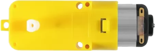
A motor is a device that converts electrical energy into mechanical energy. It is a fundamental component in countless applications, ranging from industrial machinery to consumer electronics. Motors are used to drive mechanical systems, such as conveyor belts, fans, pumps, and robotic arms. They are available in various types, including DC motors, AC motors, stepper motors, and servo motors, each suited for specific use cases.
Common applications of motors include:
- Robotics and automation systems
- HVAC systems (fans, compressors)
- Electric vehicles
- Industrial machinery
- Home appliances (washing machines, blenders, etc.)
Explore Projects Built with Motor

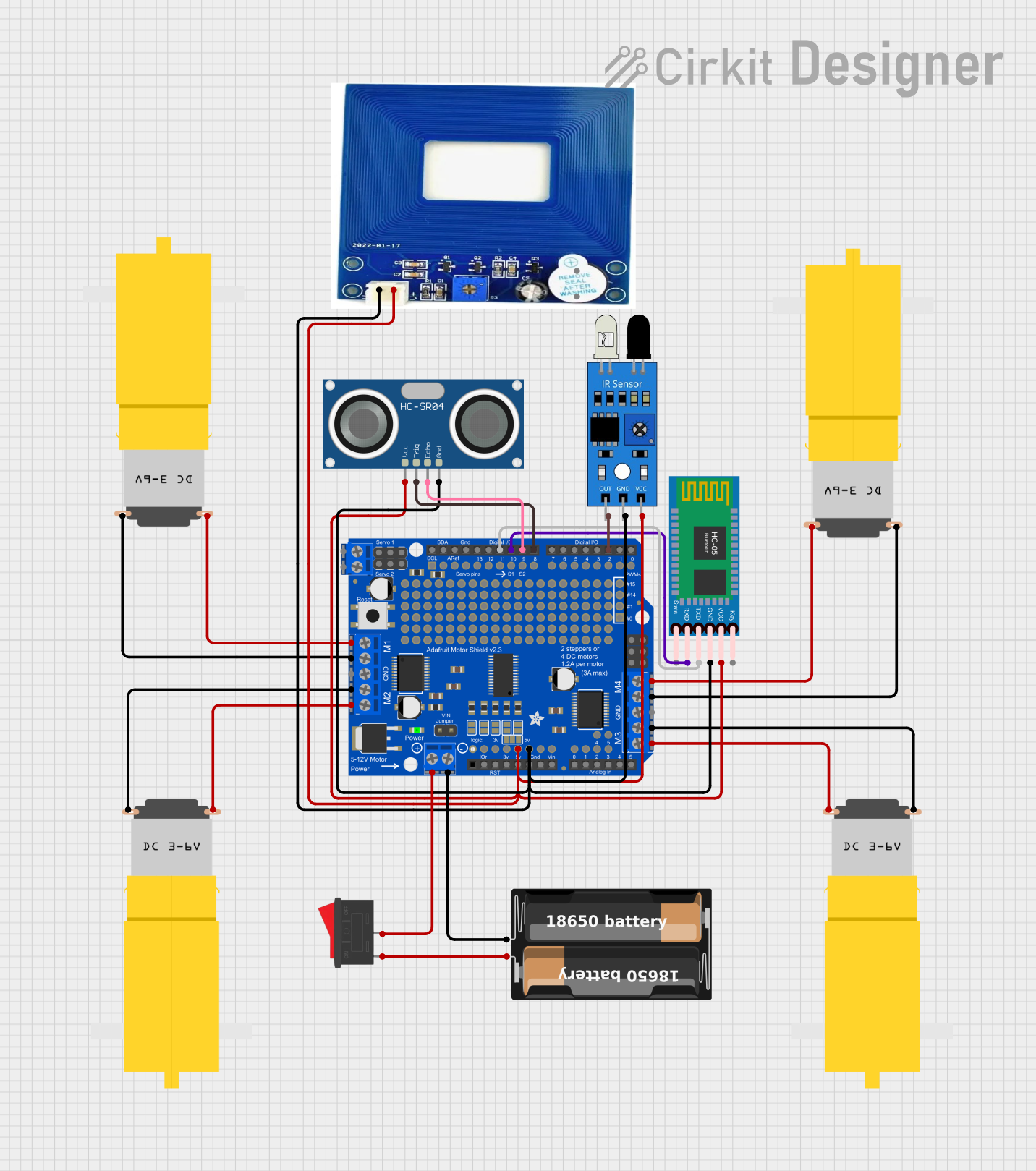
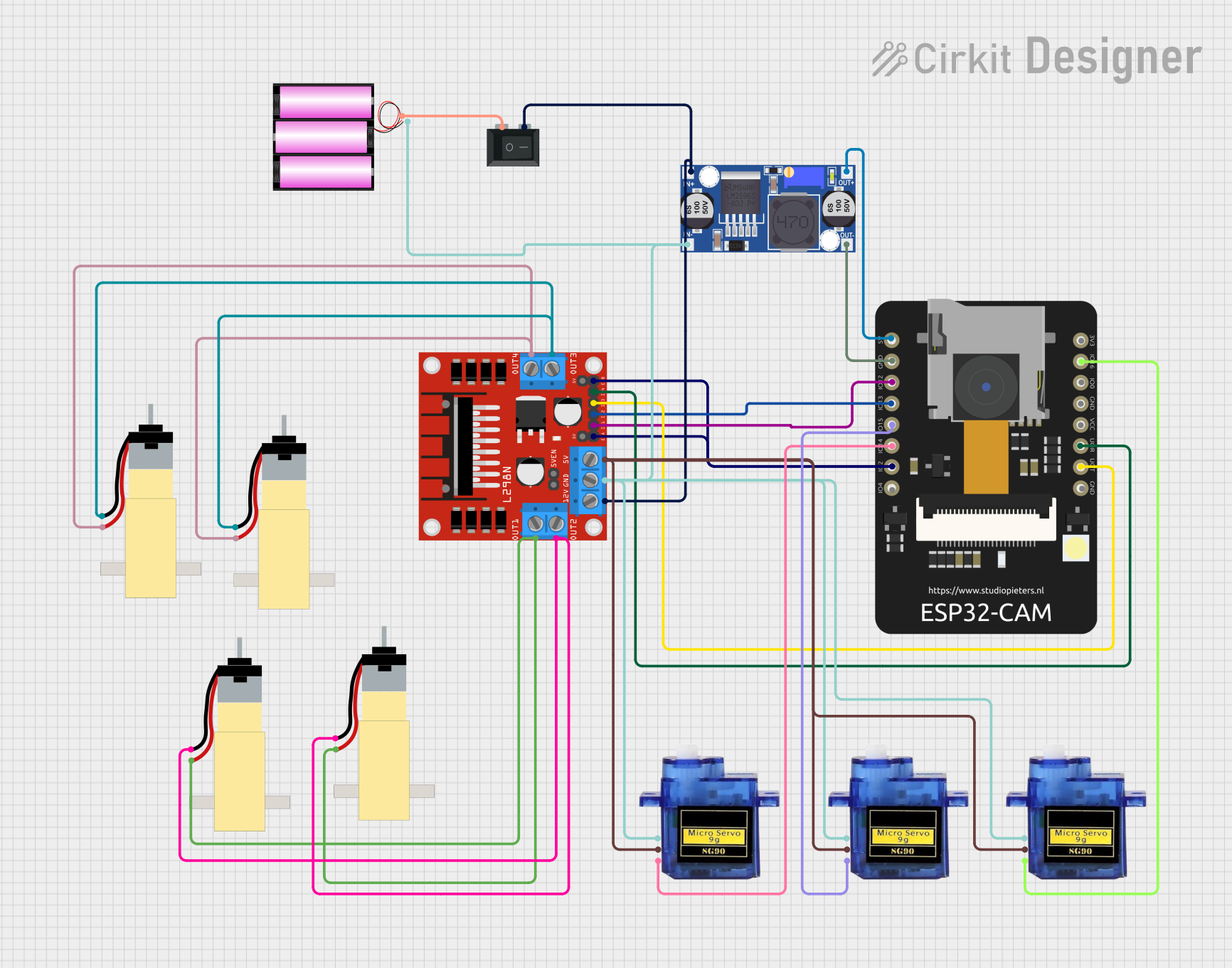
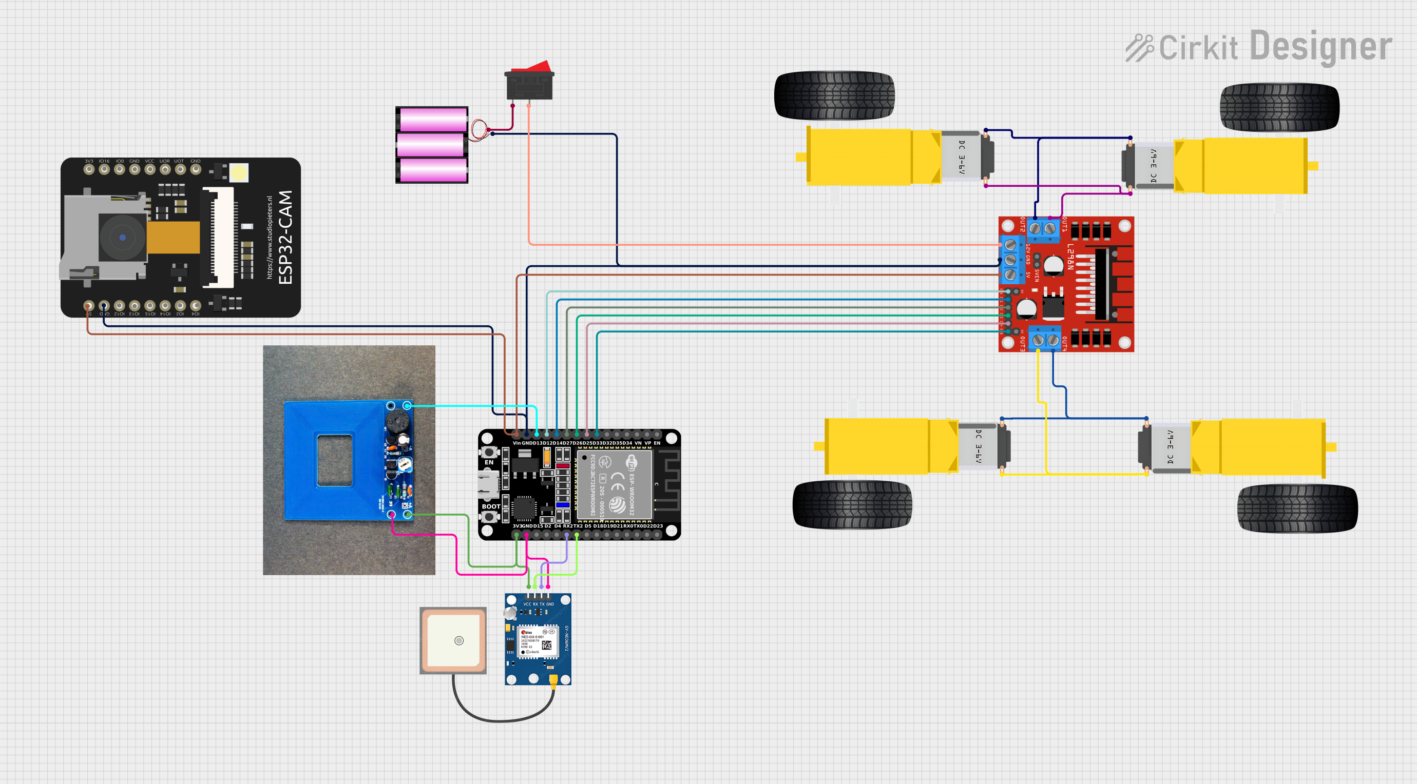
Explore Projects Built with Motor
Technical Specifications
The specifications of a motor vary depending on its type and intended application. Below is an example of a DC motor's typical technical specifications:
General Specifications
| Parameter | Value |
|---|---|
| Operating Voltage | 6V - 12V |
| Rated Current | 0.5A - 2A |
| Stall Current | 2A - 5A |
| Rated Speed | 1000 - 5000 RPM |
| Torque | 0.1 - 1.5 Nm |
| Power Output | 1W - 50W |
| Motor Type | Brushed DC Motor |
Pin Configuration (for a DC motor with encoder)
| Pin Name | Description |
|---|---|
| VCC | Power supply input (6V - 12V) |
| GND | Ground connection |
| Motor+ | Positive terminal for motor winding |
| Motor- | Negative terminal for motor winding |
| Encoder A | Encoder output signal A (for speed/direction) |
| Encoder B | Encoder output signal B (for speed/direction) |
Usage Instructions
How to Use a Motor in a Circuit
- Power Supply: Ensure the motor is powered with the correct voltage and current as per its specifications. Use a motor driver or H-bridge circuit to control the motor safely.
- Connections:
- Connect the motor terminals (Motor+ and Motor-) to the output of the motor driver.
- If the motor has an encoder, connect the encoder pins (Encoder A and Encoder B) to the microcontroller for feedback.
- Control: Use a microcontroller (e.g., Arduino UNO) to send control signals to the motor driver. This allows you to control the motor's speed and direction.
Important Considerations
- Current Limiting: Motors can draw high current during startup or under load. Use a motor driver with current-limiting features to protect the circuit.
- Heat Dissipation: Motors can generate heat during operation. Ensure proper ventilation or heat sinks to prevent overheating.
- Power Supply: Use a power supply capable of providing sufficient current for the motor's operation.
- Noise Suppression: Add capacitors across the motor terminals to reduce electrical noise.
Example: Controlling a DC Motor with Arduino UNO
Below is an example of how to control a DC motor using an Arduino UNO and an L298N motor driver.
// Example: Controlling a DC motor with Arduino UNO and L298N motor driver

// Define motor control pins
const int motorPin1 = 9; // Motor input pin 1
const int motorPin2 = 10; // Motor input pin 2
const int enablePin = 11; // Enable pin for motor speed control

void setup() {
  // Set motor pins as outputs
  pinMode(motorPin1, OUTPUT);
  pinMode(motorPin2, OUTPUT);
  pinMode(enablePin, OUTPUT);
}

void loop() {
  // Rotate motor in forward direction
  digitalWrite(motorPin1, HIGH); // Set pin 1 HIGH
  digitalWrite(motorPin2, LOW);  // Set pin 2 LOW
  analogWrite(enablePin, 128);   // Set speed (0-255)

  delay(2000); // Run motor for 2 seconds

  // Rotate motor in reverse direction
  digitalWrite(motorPin1, LOW);  // Set pin 1 LOW
  digitalWrite(motorPin2, HIGH); // Set pin 2 HIGH
  analogWrite(enablePin, 128);   // Set speed (0-255)

  delay(2000); // Run motor for 2 seconds

  // Stop the motor
  digitalWrite(motorPin1, LOW);  // Set pin 1 LOW
  digitalWrite(motorPin2, LOW);  // Set pin 2 LOW
  analogWrite(enablePin, 0);     // Set speed to 0

  delay(2000); // Wait for 2 seconds before repeating
}
Troubleshooting and FAQs
Common Issues
Motor Not Spinning:
- Check the power supply voltage and current.
- Verify the motor driver connections and ensure the control signals are correct.
- Inspect the motor for physical damage or obstructions.
Motor Overheating:
- Ensure the motor is not overloaded.
- Check for proper ventilation or add a heat sink.
Noisy Operation:
- Add capacitors (e.g., 0.1µF) across the motor terminals to suppress noise.
- Ensure the motor is securely mounted to reduce vibrations.
Inconsistent Speed:
- Verify the power supply stability.
- If using an encoder, check the encoder connections and signal integrity.
FAQs
Q: Can I connect a motor directly to a microcontroller?
A: No, motors typically require more current than a microcontroller can provide. Use a motor driver or H-bridge circuit to control the motor.
Q: How do I reverse the motor's direction?
A: Swap the polarity of the motor terminals or use a motor driver to control the direction programmatically.
Q: What is the purpose of an encoder in a motor?
A: An encoder provides feedback on the motor's speed and position, enabling precise control in applications like robotics.
Q: Can I use a single power supply for both the motor and microcontroller?
A: Yes, but ensure the power supply can handle the combined current requirements of both components. Use decoupling capacitors to reduce noise.