Cirkit Designer Logo
Cirkit Designer
Your all-in-one circuit design IDE
Home / 
Component Documentation

How to Use Microbit: Examples, Pinouts, and Specs

Image of Microbit
Cirkit Designer LogoDesign with Microbit in Cirkit Designer

Introduction

The Microbit is a small, programmable microcontroller board designed for educational purposes. Manufactured by Arduino with the part ID "UNO," it is an excellent tool for teaching coding, electronics, and problem-solving skills. The Microbit features an array of built-in sensors, buttons, and LED lights, making it a versatile platform for beginners and experienced users alike.

Explore Projects Built with Microbit

Use Cirkit Designer to design, explore, and prototype these projects online. Some projects support real-time simulation. Click "Open Project" to start designing instantly!
Adafruit Crickit Controlled Robotics Platform with Micro:bit
Image of Circuit Design for Recyclo-Bot: A project utilizing Microbit in a practical application
This circuit is designed to control multiple motors and servos using an Adafruit Crickit for microbit as the main controller, interfaced with a micro bit microcontroller. It includes two yellow hobby gear motors, two 9G micro servos, and two standard servos, all powered and controlled by the Crickit board. Additionally, there is a 0.96" OLED display for output and a piezo sensor, likely for input, connected to the Crickit, which is programmed via the micro bit.
Cirkit Designer LogoOpen Project in Cirkit Designer
I2C-Controlled OLED Display with External EEPROM and Interactive Pushbuttons
Image of godmode: A project utilizing Microbit in a practical application
This is a microcontroller-based interactive device featuring a Wemos D1 Mini, an OLED display, external EEPROM, and an I/O expander. It includes user input buttons and status LEDs, with potential MIDI interface capabilities.
Cirkit Designer LogoOpen Project in Cirkit Designer
Bluetooth-Controlled Multi-Function Arduino Nano Gadget
Image of Copy of Smarttt: A project utilizing Microbit in a practical application
This is a portable, microcontroller-driven interactive device featuring Bluetooth connectivity, visual (RGB LED), auditory (loudspeaker), and haptic (vibration motor) feedback, user input (pushbutton), and a rechargeable power system (TP4056 with Li-ion battery).
Cirkit Designer LogoOpen Project in Cirkit Designer
ATmega328P-Based Sensor Hub with OLED Display and LIDAR
Image of TILTPCB: A project utilizing Microbit in a practical application
This circuit features an Mtiny Uno ATmega328P microcontroller as its central processing unit, interfacing with a variety of sensors and peripherals. It includes a 0.96" OLED display and an MPU6050 accelerometer/gyroscope for user interface and motion sensing, respectively. The circuit also integrates a TF LUNA LIDAR for distance measurement, a DHT11 sensor for temperature and humidity readings, and uses a 9V battery with a 7805 voltage regulator for power management. Communication with a computer for programming and data exchange is facilitated by an Adafruit FTDI Friend module.
Cirkit Designer LogoOpen Project in Cirkit Designer

Explore Projects Built with Microbit

Use Cirkit Designer to design, explore, and prototype these projects online. Some projects support real-time simulation. Click "Open Project" to start designing instantly!
Image of Circuit Design for Recyclo-Bot: A project utilizing Microbit in a practical application
Adafruit Crickit Controlled Robotics Platform with Micro:bit
This circuit is designed to control multiple motors and servos using an Adafruit Crickit for microbit as the main controller, interfaced with a micro bit microcontroller. It includes two yellow hobby gear motors, two 9G micro servos, and two standard servos, all powered and controlled by the Crickit board. Additionally, there is a 0.96" OLED display for output and a piezo sensor, likely for input, connected to the Crickit, which is programmed via the micro bit.
Cirkit Designer LogoOpen Project in Cirkit Designer
Image of godmode: A project utilizing Microbit in a practical application
I2C-Controlled OLED Display with External EEPROM and Interactive Pushbuttons
This is a microcontroller-based interactive device featuring a Wemos D1 Mini, an OLED display, external EEPROM, and an I/O expander. It includes user input buttons and status LEDs, with potential MIDI interface capabilities.
Cirkit Designer LogoOpen Project in Cirkit Designer
Image of Copy of Smarttt: A project utilizing Microbit in a practical application
Bluetooth-Controlled Multi-Function Arduino Nano Gadget
This is a portable, microcontroller-driven interactive device featuring Bluetooth connectivity, visual (RGB LED), auditory (loudspeaker), and haptic (vibration motor) feedback, user input (pushbutton), and a rechargeable power system (TP4056 with Li-ion battery).
Cirkit Designer LogoOpen Project in Cirkit Designer
Image of TILTPCB: A project utilizing Microbit in a practical application
ATmega328P-Based Sensor Hub with OLED Display and LIDAR
This circuit features an Mtiny Uno ATmega328P microcontroller as its central processing unit, interfacing with a variety of sensors and peripherals. It includes a 0.96" OLED display and an MPU6050 accelerometer/gyroscope for user interface and motion sensing, respectively. The circuit also integrates a TF LUNA LIDAR for distance measurement, a DHT11 sensor for temperature and humidity readings, and uses a 9V battery with a 7805 voltage regulator for power management. Communication with a computer for programming and data exchange is facilitated by an Adafruit FTDI Friend module.
Cirkit Designer LogoOpen Project in Cirkit Designer

Common Applications and Use Cases

  • Teaching programming and electronics in schools
  • Prototyping simple IoT (Internet of Things) devices
  • Interactive projects such as games, wearables, and robotics
  • Data collection and analysis using built-in sensors
  • Wireless communication between devices using Bluetooth

Technical Specifications

The Microbit is packed with features that make it a powerful yet user-friendly tool for learning and prototyping. Below are its key technical specifications:

General Specifications

Feature Description
Microcontroller ARM Cortex-M0
Operating Voltage 3.3V
Input Voltage (via USB) 5V
Flash Memory 256 KB
RAM 16 KB
Connectivity Bluetooth Low Energy (BLE), USB
Dimensions 52mm x 43mm

Pin Configuration and Descriptions

The Microbit has an edge connector with 25 pins, including GPIO, power, and communication pins. Below is a summary of the most commonly used pins:

Pin Number Name Description
0 P0 General-purpose I/O pin, often used for sensors
1 P1 General-purpose I/O pin
2 P2 General-purpose I/O pin
3V 3.3V Power output for external components
GND Ground Common ground for the circuit
SCL I2C Clock I2C communication clock line
SDA I2C Data I2C communication data line

Usage Instructions

The Microbit is designed to be easy to use, even for beginners. Follow these steps to get started:

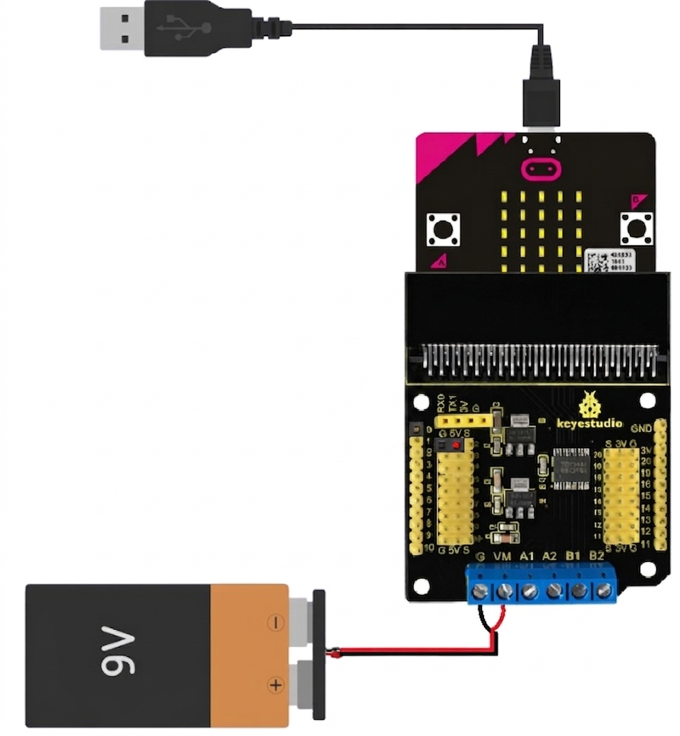
Step 1: Powering the Microbit

  • Connect the Microbit to your computer using a micro-USB cable. This will power the board and allow you to program it.
  • Alternatively, you can power the Microbit using a battery pack (3V).

Step 2: Programming the Microbit

  • Use the Arduino IDE or the Microbit's online MakeCode editor to write and upload code.
  • The Microbit supports multiple programming languages, including Python, JavaScript, and C++.

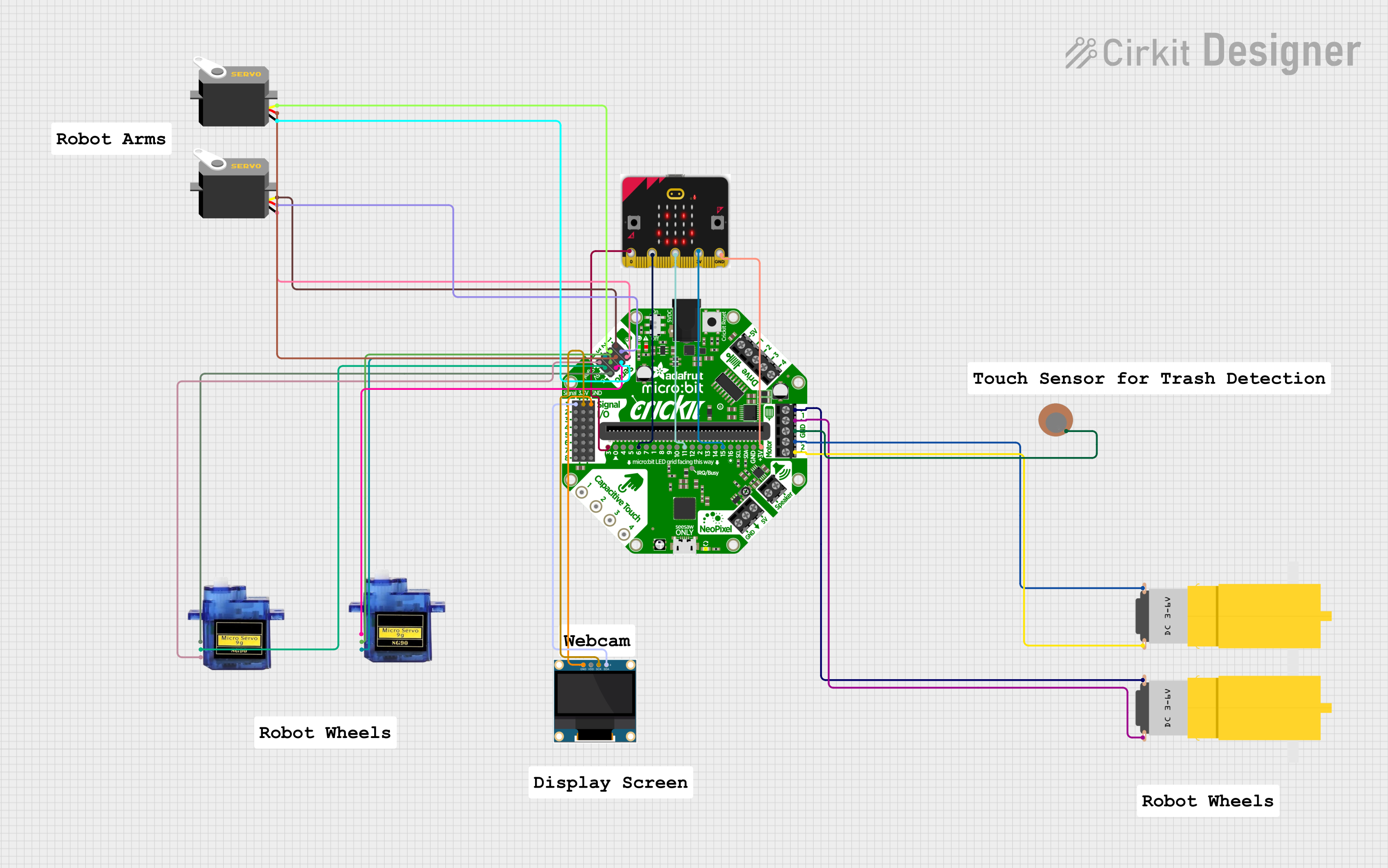
Step 3: Connecting External Components

  • Use alligator clips or a breakout board to connect external components like LEDs, sensors, or motors to the Microbit's edge connector.
  • Ensure that the components are compatible with the Microbit's 3.3V operating voltage.

Example Code: Blinking an LED

Below is an example of how to blink an LED connected to pin P0 using the Arduino IDE:

// This code blinks an LED connected to pin P0 of the Microbit.
// Ensure the LED's longer leg (anode) is connected to P0 and the shorter leg 
// (cathode) is connected to GND.

void setup() {
  pinMode(0, OUTPUT); // Set pin P0 as an output
}

void loop() {
  digitalWrite(0, HIGH); // Turn the LED on
  delay(1000);           // Wait for 1 second
  digitalWrite(0, LOW);  // Turn the LED off
  delay(1000);           // Wait for 1 second
}

Best Practices

  • Avoid connecting components that draw more current than the Microbit can supply.
  • Use resistors with LEDs to prevent damage to the Microbit's pins.
  • When using Bluetooth, ensure that the Microbit is not connected to USB, as this may interfere with communication.

Troubleshooting and FAQs

Common Issues

  1. The Microbit is not detected by the computer.

    • Ensure the USB cable is not just a charging cable but also supports data transfer.
    • Try connecting to a different USB port or using a different cable.
  2. The program does not run after uploading.

    • Verify that the code is error-free and compatible with the Microbit.
    • Ensure the Microbit is properly powered.
  3. External components are not working.

    • Check the wiring and ensure components are connected to the correct pins.
    • Verify that the components are compatible with the Microbit's 3.3V operating voltage.

Tips for Troubleshooting

  • Use the Microbit's built-in LED matrix to display error codes or debug information.
  • Test the Microbit with a simple program (e.g., blinking an LED) to ensure it is functioning correctly.
  • Consult the Microbit's official documentation and community forums for additional support.

By following this documentation, you can effectively use the Microbit for a wide range of educational and prototyping projects.