How to Use contactor: Examples, Pinouts, and Specs
Introduction
A contactor is an electromechanical switch in electrical engineering, used primarily for switching an electrical power circuit. Unlike relays, contactors are designed to connect and disconnect large electrical loads, often in industrial and commercial settings. They are controlled by a circuit with a much lower power level than the switched circuit.
Explore Projects Built with contactor


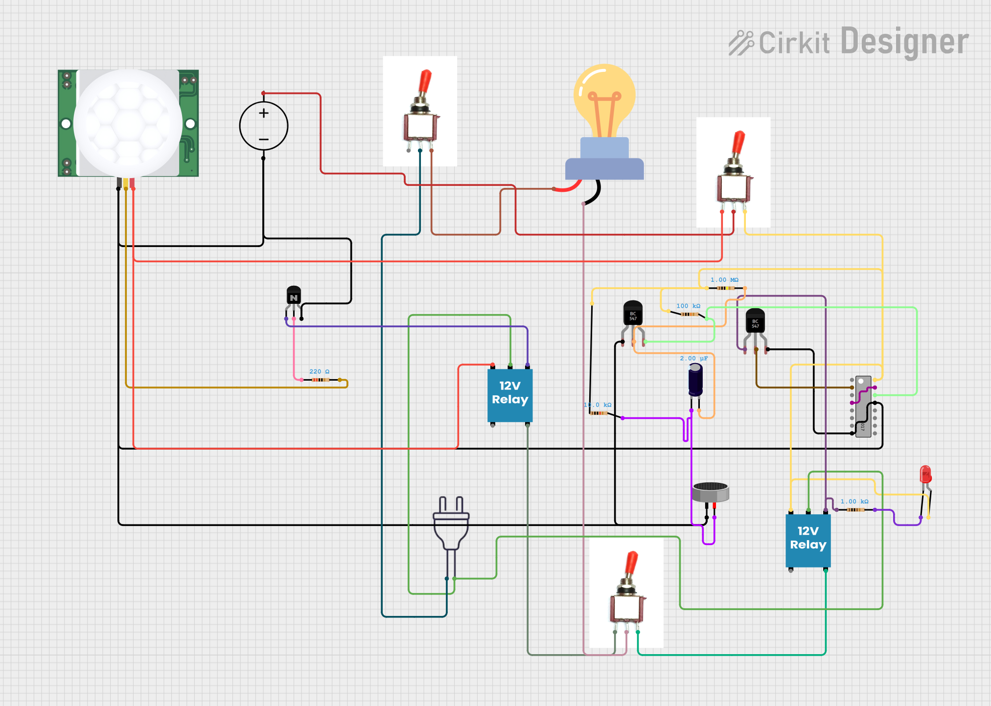
Explore Projects Built with contactor
Common Applications and Use Cases
- Motor control
- Lighting control
- Heating
- Capacitor banks switching
- Electric vehicle charging stations
- Power distribution
Technical Specifications
Key Technical Details
- Rated Voltage: Specified in volts (V), the maximum voltage the contactor can handle.
- Rated Current: Specified in amperes (A), the maximum current the contactor can conduct.
- Power Ratings: Specified in kilowatts (kW) or horsepower (HP), indicating the maximum power load.
- Control Voltage: The voltage required to activate the coil.
- Number of Poles: Indicates how many circuits the contactor can control.
- Contact Material: Usually silver alloy for good conductivity and durability.
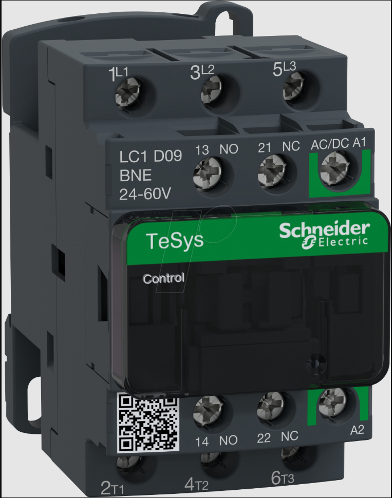
Pin Configuration and Descriptions
| Pin Number | Description | Notes |
|---|---|---|
| A1 | Coil connection (positive) | Control voltage applied here |
| A2 | Coil connection (negative) | Control circuit ground |
| 1, 3, 5 | Power circuit connections | Input terminals for power circuit |
| 2, 4, 6 | Power circuit connections | Output terminals to load |
| NC | Normally Closed Contact | Closed when contactor is off |
| NO | Normally Open Contact | Closed when contactor is on |
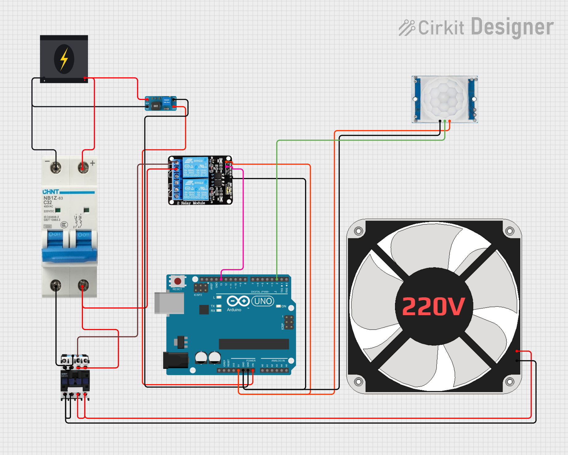
Usage Instructions
How to Use the Contactor in a Circuit
- Power Circuit Connection: Connect the power source to the input terminals (1, 3, 5) and the load to the output terminals (2, 4, 6).
- Control Circuit Connection: Apply the control voltage between terminals A1 and A2. Ensure that the control voltage matches the contactor's coil rating.
- Activation: When the control voltage is applied, the coil gets energized, and the contactor closes the power circuit, allowing current to flow to the load.
Important Considerations and Best Practices
- Always disconnect power before working on the contactor.
- Ensure the contactor's ratings match the application requirements.
- Use appropriate cable sizes to handle the expected current.
- Consider using an interposing relay if the control signal is weak or comes from a sensitive electronic device.
- Regularly inspect the contactor for signs of wear or damage, especially the contacts and coil.
Troubleshooting and FAQs
Common Issues
- Contactor Coil Does Not Energize: Check control circuit for proper voltage and connections.
- Contacts Not Closing or Opening Properly: Inspect for physical obstructions or burnt contacts.
- Excessive Noise or Chatter: Verify that the control voltage is stable and within the specified range.
Solutions and Tips for Troubleshooting
- Ensure all connections are secure and free from corrosion.
- Test the coil with a multimeter to ensure it has continuity.
- If the contacts are worn or damaged, consider replacing the contactor.
- Use a surge suppressor to protect the coil from voltage spikes.
FAQs
Q: Can a contactor be used for DC applications? A: Yes, but ensure the contactor is rated for DC operation as DC and AC ratings may differ.
Q: How do I size a contactor for my application? A: Size the contactor based on the maximum current and voltage requirements of the load, with some margin for safety.
Q: What is the life expectancy of a contactor? A: It varies based on usage frequency and environmental conditions but typically ranges from thousands to millions of operations.
Note: This documentation is for a generic contactor manufactured by Electrical with the part ID Rover. For specific models, refer to the manufacturer's datasheet.
Disclaimer: This documentation is provided "as is" without any warranty of any kind, either expressed or implied. The user assumes the entire risk as to the accuracy and the use of this document.