Cirkit Designer Logo
Cirkit Designer
Your all-in-one circuit design IDE
Home / 
Component Documentation

How to Use AS3400: Examples, Pinouts, and Specs
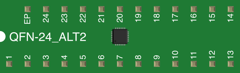

Image of AS3400
Cirkit Designer LogoDesign with AS3400 in Cirkit Designer

Introduction

The AS3400 is a high-performance operational amplifier (op-amp) manufactured by ams. It is designed for precision signal processing applications, offering low noise, high gain, and a wide bandwidth. These features make the AS3400 an ideal choice for applications requiring accurate and reliable signal amplification, such as audio systems, instrumentation, and control systems.

Explore Projects Built with AS3400

Use Cirkit Designer to design, explore, and prototype these projects online. Some projects support real-time simulation. Click "Open Project" to start designing instantly!
Satellite-Based Timing and Navigation System with SDR and Atomic Clock Synchronization
Image of GPS 시스템 측정 구성도_Confirm: A project utilizing AS3400 in a practical application
This circuit appears to be a complex system involving power supply management, GPS and timing synchronization, and data communication. It includes a SI-TEX G1 Satellite Compass for GPS data, an XHTF1021 Atomic Rubidium Clock for precise timing, and Ettus USRP B200 units for software-defined radio communication. Power is supplied through various SMPS units and distributed via terminal blocks and DC jacks. Data communication is facilitated by Beelink MINI S12 N95 computers, RS232 splitters, and a 1000BASE-T Media Converter for network connectivity. RF Directional Couplers are used to interface antennas with the USRP units, and the entire system is likely contained within cases for protection and organization.
Cirkit Designer LogoOpen Project in Cirkit Designer
Satellite Compass and Network-Integrated GPS Data Processing System
Image of GPS 시스템 측정 구성도_241016: A project utilizing AS3400 in a practical application
This circuit comprises a satellite compass, a mini PC, two GPS antennas, power supplies, a network switch, media converters, and an atomic rubidium clock. The satellite compass is powered by a triple output DC power supply and interfaces with an RS232 splitter for 1PPS signals. The mini PCs are connected to the USRP B200 devices via USB for data and power, and to media converters via Ethernet, which in turn connect to a network switch using fiber optic links. The antennas are connected to the USRP B200s through RF directional couplers, and the atomic clock provides a 1PPS input to the RS232 splitter.
Cirkit Designer LogoOpen Project in Cirkit Designer
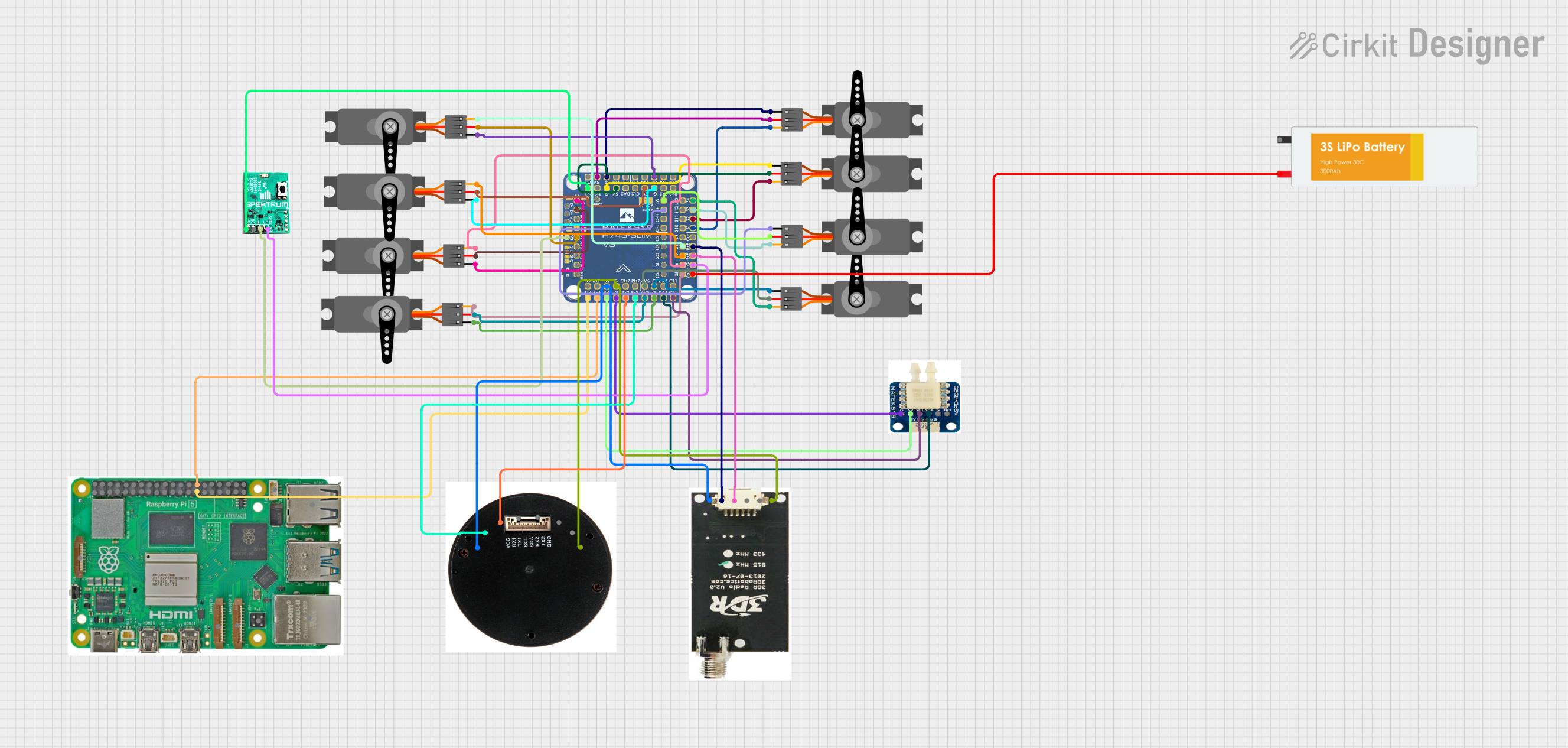
Raspberry Pi and H743-SLIM V3 Controlled Servo System with GPS and Telemetry
Image of Avionics Wiring Diagram: A project utilizing AS3400 in a practical application
This circuit is designed for a UAV control system, featuring an H743-SLIM V3 flight controller connected to multiple servos for control surfaces, a GPS module for navigation, a telemetry radio for communication, and a digital airspeed sensor for flight data. The system is powered by a LiPo battery and includes a Raspberry Pi for additional processing and control tasks.
Cirkit Designer LogoOpen Project in Cirkit Designer
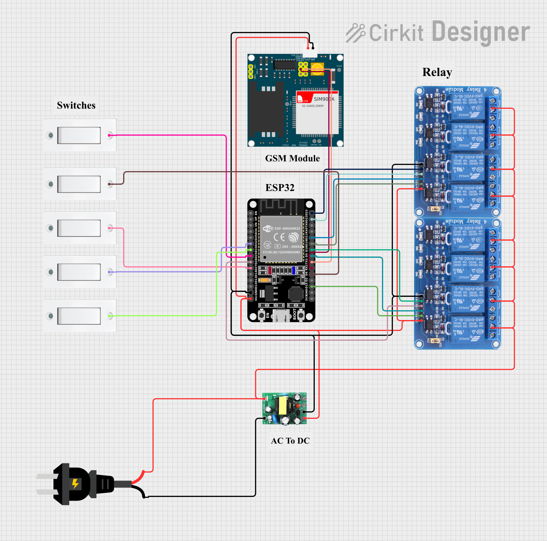
ESP32 and SIM900A Based Smart Home Automation with Wi-Fi and GSM Control
Image of iot: A project utilizing AS3400 in a practical application
This circuit features an ESP32 microcontroller interfaced with multiple flush switches and two 4-channel relay modules to control various loads. It also includes a SIM900A module for GSM communication and an AC to DC converter for power management. The ESP32 handles input from the switches and controls the relays, while the SIM900A provides remote communication capabilities.
Cirkit Designer LogoOpen Project in Cirkit Designer

Explore Projects Built with AS3400

Use Cirkit Designer to design, explore, and prototype these projects online. Some projects support real-time simulation. Click "Open Project" to start designing instantly!
Image of GPS 시스템 측정 구성도_Confirm: A project utilizing AS3400 in a practical application
Satellite-Based Timing and Navigation System with SDR and Atomic Clock Synchronization
This circuit appears to be a complex system involving power supply management, GPS and timing synchronization, and data communication. It includes a SI-TEX G1 Satellite Compass for GPS data, an XHTF1021 Atomic Rubidium Clock for precise timing, and Ettus USRP B200 units for software-defined radio communication. Power is supplied through various SMPS units and distributed via terminal blocks and DC jacks. Data communication is facilitated by Beelink MINI S12 N95 computers, RS232 splitters, and a 1000BASE-T Media Converter for network connectivity. RF Directional Couplers are used to interface antennas with the USRP units, and the entire system is likely contained within cases for protection and organization.
Cirkit Designer LogoOpen Project in Cirkit Designer
Image of GPS 시스템 측정 구성도_241016: A project utilizing AS3400 in a practical application
Satellite Compass and Network-Integrated GPS Data Processing System
This circuit comprises a satellite compass, a mini PC, two GPS antennas, power supplies, a network switch, media converters, and an atomic rubidium clock. The satellite compass is powered by a triple output DC power supply and interfaces with an RS232 splitter for 1PPS signals. The mini PCs are connected to the USRP B200 devices via USB for data and power, and to media converters via Ethernet, which in turn connect to a network switch using fiber optic links. The antennas are connected to the USRP B200s through RF directional couplers, and the atomic clock provides a 1PPS input to the RS232 splitter.
Cirkit Designer LogoOpen Project in Cirkit Designer
Image of Avionics Wiring Diagram: A project utilizing AS3400 in a practical application
Raspberry Pi and H743-SLIM V3 Controlled Servo System with GPS and Telemetry
This circuit is designed for a UAV control system, featuring an H743-SLIM V3 flight controller connected to multiple servos for control surfaces, a GPS module for navigation, a telemetry radio for communication, and a digital airspeed sensor for flight data. The system is powered by a LiPo battery and includes a Raspberry Pi for additional processing and control tasks.
Cirkit Designer LogoOpen Project in Cirkit Designer
Image of iot: A project utilizing AS3400 in a practical application
ESP32 and SIM900A Based Smart Home Automation with Wi-Fi and GSM Control
This circuit features an ESP32 microcontroller interfaced with multiple flush switches and two 4-channel relay modules to control various loads. It also includes a SIM900A module for GSM communication and an AC to DC converter for power management. The ESP32 handles input from the switches and controls the relays, while the SIM900A provides remote communication capabilities.
Cirkit Designer LogoOpen Project in Cirkit Designer

Common Applications

  • Audio signal amplification
  • Precision instrumentation
  • Control systems
  • Sensor signal conditioning
  • Active filters and oscillators

Technical Specifications

Key Specifications

Parameter Value
Supply Voltage Range ±2.5V to ±18V
Input Offset Voltage 0.5 mV (typical)
Input Bias Current 10 nA (typical)
Gain Bandwidth Product 10 MHz
Slew Rate 5 V/µs
Output Voltage Swing ±(Vcc - 1.5V)
Noise Density 4 nV/√Hz @ 1 kHz
Operating Temperature -40°C to +85°C
Package Options SOIC-8, TSSOP-8

Pin Configuration and Descriptions

The AS3400 is typically available in an 8-pin SOIC or TSSOP package. The pinout is as follows:

Pin Number Pin Name Description
1 Offset Null 1 Offset voltage adjustment (connect to a pot)
2 Inverting Input Inverting input terminal (-)
3 Non-Inverting Input Non-inverting input terminal (+)
4 V- (GND) Negative power supply or ground
5 Offset Null 2 Offset voltage adjustment (connect to a pot)
6 Output Amplified output signal
7 V+ Positive power supply
8 NC (No Connect) Not connected internally

Usage Instructions

Using the AS3400 in a Circuit

  1. Power Supply: Connect the AS3400 to a dual power supply (e.g., ±12V) or a single supply (e.g., 5V and GND) depending on your application. Ensure the supply voltage is within the specified range (±2.5V to ±18V).
  2. Input Connections:
    • Connect the signal source to the non-inverting input (Pin 3) for a non-inverting amplifier configuration.
    • For an inverting amplifier, connect the signal source to the inverting input (Pin 2) through a resistor.
  3. Feedback Network: Use appropriate resistors and capacitors in the feedback loop to set the desired gain and bandwidth.
  4. Offset Adjustment: If required, connect a potentiometer between Offset Null 1 (Pin 1) and Offset Null 2 (Pin 5) to fine-tune the input offset voltage.
  5. Output Load: Ensure the load connected to the output (Pin 6) does not exceed the op-amp's drive capability.

Example Circuit: Non-Inverting Amplifier

Below is an example of a non-inverting amplifier circuit using the AS3400:

       +Vcc
        |
        |
        Rf
        |
Input --+----+---- Output
             |
             Rg
             |
            GND

Where:

  • Rf is the feedback resistor.
  • Rg is the resistor connected to ground.
  • Gain = 1 + (Rf / Rg).

Arduino UNO Example Code

The AS3400 can be used with an Arduino UNO for signal amplification. Below is an example code snippet to read an amplified signal from the AS3400:

// Arduino code to read an amplified signal from the AS3400
const int analogPin = A0; // Connect AS3400 output to Arduino A0 pin

void setup() {
  Serial.begin(9600); // Initialize serial communication at 9600 baud
}

void loop() {
  int sensorValue = analogRead(analogPin); // Read the analog signal
  float voltage = sensorValue * (5.0 / 1023.0); // Convert to voltage
  Serial.print("Amplified Signal Voltage: ");
  Serial.println(voltage); // Print the voltage to the Serial Monitor
  delay(500); // Wait for 500ms before the next reading
}

Important Considerations

  • Use decoupling capacitors (e.g., 0.1 µF ceramic) close to the power supply pins to reduce noise.
  • Avoid exceeding the maximum input voltage range to prevent damage to the op-amp.
  • Ensure proper grounding to minimize noise and interference.

Troubleshooting and FAQs

Common Issues and Solutions

  1. No Output Signal:

    • Verify the power supply connections and ensure the voltage is within the specified range.
    • Check the input signal and ensure it is within the op-amp's input voltage range.
    • Inspect the feedback network for proper connections.
  2. Distorted Output:

    • Ensure the load connected to the output does not exceed the op-amp's drive capability.
    • Check for oscillations caused by improper feedback network design. Add a small capacitor in parallel with the feedback resistor if necessary.
  3. High Noise in Output:

    • Use proper shielding and grounding techniques to minimize noise.
    • Add bypass capacitors near the power supply pins.

FAQs

Q: Can the AS3400 operate with a single power supply?
A: Yes, the AS3400 can operate with a single supply, but the input and output signals must remain within the specified voltage range.

Q: What is the maximum gain achievable with the AS3400?
A: The maximum gain depends on the feedback network design and the gain-bandwidth product (10 MHz). For high gains, ensure the bandwidth requirements of your application are met.

Q: How do I adjust the offset voltage?
A: Connect a 10 kΩ potentiometer between Offset Null 1 (Pin 1) and Offset Null 2 (Pin 5), with the wiper connected to Vcc or GND, to fine-tune the offset voltage.

Q: Is the AS3400 suitable for audio applications?
A: Yes, the AS3400's low noise and high gain make it an excellent choice for audio signal amplification.